Have you ever considered the manufacturing standards required for sterile products such as medication or medical appliances? Food and pharmaceutical manufacturing facilities require higher quality of air because the products are ingested or placed in humans and animals. The final product must be free of particles, microorganisms, water, and oil. It is the manufacturers responsibility to ensure the quality of the product that is produced.
The possible contaminants in compressed air in a manufacturing environment include: particles, microorganisms, water, and oil. The air quality is the measure of these contaminants in the compressed air. An official publication, containing a list of medicinal drugs with their effects and directions for their use (called a pharmacopoeia) – have relatively inaccurate qualities compared to the standards required for pharmaceutical water (Requirements for compressed Air in the Pharmaceutical Industry, retrieved November 2, 2018). Since the requirements are inaccurate, mistakes are made, unnecessary expensive and inefficient designs are implemented; specifically, in the following situations:
sterile compressed air is not a requirement to manufacture all pharmaceutical products or an entire plant.
oil free compressed air – standards do not set reasonable mg/m3 limits.
In most cases, compressed air contacts the product. As the pharmaceutical industry has grown, so too has the use of compressed air for breathing air, equipment, and instrument air operation. The USA accounts for about half of the global pharmaceutical market. Each facility has unique needs so different standards apply. The ultimate goals are guaranteeing compliance with standards, levels of safety, and quality set forth by the FDA and other regulatory entities. Many of the standards in the food industry also apply to the pharmaceutical industry as they both pertains to things human may consume.
To apply the appropriate regulatory process to for compressed air and pharmaceutical management systems, it is worth noting the following regulatory organizations and standards:
Regulatory Body/Standard
Guidelines
European Pharmacopoeia for Medical Air standard
“Oil: maximum 0.1mg/m³, determined using an oil detector tube when an oil lubricated compressor is used for the production.” Note: the color change of sulfuric acid absorber is very hard to detect.
BCAS-British Compressed Air Society standard
1. Direct Contact of air with the product: Particles: water: oil = 2:2:1 (as per ISO 8753-1) 2. Indirect Contact of Air with the Product: 2:4:2 (Validation of System for Air Quality, retrieved November 2, 2018)
American Pharmacopoeia for Testing water or oil
Let gas flow over a clean surface and check for oil streaks and/or water droplet formation.
ISO 8573 – Class 1 (2010) and Class 2
It is an international standard that:
Categorizes air quality into different classes.
Specifies maximum permissible contamination levels for each class.
Each class refers to certain Industrial applications.
This standard states that no particle larger than 5 µm is permitted in classes 1-5
Indirect and Direct Product Contact standard
An Indirect Impact System is a system that is not expected to have direct impact on quality of product, but typically supports a Direct Impact System.
A Direct Impact system is a system that has a direct impact on product quality. In what I call a “standard pharmaceutical scenario,” we are dealing with a product that is sensitive to temperature, has published storage specifications from stability studies, and the product will be considered adulterated if the manufacturer is unable to prove, through gap-free records, that the product was stored within the published storage specs.
The sources of contaminants in compressed air manufacturing environments are:
Sources of oil that could exceed the 0.1 mg/m3 requirement include:
Leakage spray near the air intake of the compressor
Emergency diesel generator being tested
Traffic jam on a nearby highway.
Oil could be hydrocarbons oxidized to CO2, oil aerosols, or vapor, which could reach the compressed air via the compressor.
Relative Humidity is a source of moisture in the air
Micron size particles are naturally in the air
Corrosion particles flake off due to high flow rate.
Impacts of Contaminants
One cubic meter of untreated compressed air may contain close to 200 million dirt particles and other substances like water, oil, lead, cadmium and mercury. The impacts of contaminants in a pharmaceutical plant are:
Microbial and bacterial growth on products and equipment
Hazardous consequences to consumer health:
Corrosion Particles landing on a sterile implant or medicine.
Exposure to or ingestion of hydrocarbons
Contaminates could accumulate on manufactured products.
Corrode pipes causing blockages and reduces the life of filters, drains, and machinery in plants.
Increased energy and cost of operation.
Understanding Air Quality Factors?
The factors that need to be understood in a pharmaceutical manufacturing environment to improve air quality are:
Understand the impact of air quality on the work zone, workers, and the product or service manufactured.
Review Direct Product Contact, Indirect Product Contact, USP, and ISO 8573 air standards
Understand your requirements. Do you need a clean room in your factory? Clean room air quality is expensive to deliver and maintain.
Identify the current air quality in the non-clean environment.
Determine the air testing equipment required with sampling media
Determine the particulate control level required for your environment: size and count
Engage the production engineers who are most familiar with air quality requirements. They are the resource to determine what needs to be removed from the air and which filter to use for the correct solution. The production engineer would also know the dampness of the air required: moist or dry.
Determine the amount of moisture required in the air.
Know the type of oil present in the factory so the type of tube required for testing can be determined.
Be aware that compressed air pressure reducers and valves can also discharge particles.
This is an incomplete list of possible solutions to meet air quality standards in pharmaceutical manufacturing environments:
Develop, and regularly perform site-specific testing programs to produce valid, repeatable testing results that reinforce the site’s air quality.
Schedule routine testing for OSHA, FDA, and Current Good Manufacturing Practices (cGMP) verification and compliance at each facility
Monitor equipment for particles, moisture, and oil contaminants
Install and use oil free compressors
Use only stainless steel or aluminum pipes, which do not corrode
Monitor your intake air: decrease the RH factor and keep it clean
Use equipment that is most efficient for your factory.
NOTE: When attached to an oiled pipe – the regulations do not state that the air needs to be tested.
All factory processes do not require the same air quality standards. When manufacturing equipment that will enter a person’s body (such as knee and hip joints, defibrillators, and pacemakers), a clean room must be designed that uses a spec that ensures a heightened level of particulate control. Once the surface is clean, it must be blown with compressed air to ensure no particles are on it. Refer to ISO 8573 Class 1 or 2 requirements above for more information. If you are creating a clean room in a non-clean environment – the quality of the extremely clean air – is decreased when introduced to the non-clean environment. If the temperature is too cold, it may destroy the manufactured product by hurting or deactivating them. In other products, the moisture in the air could interact with the material resulting in issues. In these situations, extremely dry air is required. There is no single solution for all factories when considering the dew point and moisture air management.
NOTE: The dew point is the temperature that air becomes so saturated with water that if cooled further it will condense to form water.
Microbiological limit values are missing for the compressed air both in the pharmacopoeia and in the ISO 8573. The limits based on the clean room classes in which the compressed air is used should be defined, e.g. for class C the max. permissible 100KBE/m³ from Annex 1.
When using compressed air to blow out bottles prior to inserting tablets or to run machinery, the most stringent air standards is not necessary because of the expense or the difficulty to regularly test the air quality. In this situation, it is recommended a point of use filter is installed. In these cases, 1% of the factory uses very high-quality air for specific applications. The rest of the factory does not need high quality air. A point-of-use filter is the cheapest and most efficient solution for greater production.
Many factories use refrigerated air to remove water, then heat the air to room temperature so that the resulting air is low in humidity and bacterial growth.
Nex Flow works with pharmaceutical manufacturing companies to recommend the right product that complies to operational efficiency and safety.
A durable, stainless steel “Vortex tube” is used to convert compressed air into cold temperatures, as low as -50 oF (- 46 oC) to spot cool as well as to air condition an enclosure. Vortex Tubes are used when other cooling tools are not able to cool an area or an enclosure to the desired temperature. Vortex tube operated panel coolers are mounted on the top of electrical and electronic cabinets to send clean, cool air down into the panel, displacing hot air around sensitive electronics. The vortex electrical panel cooler is made of stainless steel to protect against rain, snow, humidity, outdoor use, and corrosive environments. They work best in extremely hot and hazardous environments. Vortex tubes themselves can be made of aluminum, brass or stainless steel. However,l Nex Flow® chooses to use stainless steel for longer life and durability in all factory environments.
There are three standard sizes for Nex Flow® Frigid-X® Vortex tubes:
Small: 2, 4, or 8 SCFM
Medium: 10, 15, 26, 30, and 40 SFM
Large: 10 000 BTU/hour and is used for heavy industrial uses
The tube comes assembled with a brass generator, which provides a longer lifespan in high temperature environments compared to plastic used by some manufacturers. Continuous operation of the Vortex tube compressed air panel cooler is best when constant cooling and/or a positive purge of waste/heat is required.
NOTE: The cooling effect (BTU/hr) is determined by flow and temperature drop.
All Vortex tubes have a generator which is sized for a certain flow. There are two basic types of generators – one to produce extreme cold temperatures (maximum cold temperature out called the C generator) and another type to produce maximum amount of cooling (maximum refrigeration called the H generator). The Vortex Tube takes compressed air and converts it to cold air as low as minus 50° F (minus 46° C) at one end and hot air at the other up to 260° F (127° C). If cooling effect is important to the manufacturing application, then the cold air flowing out of the Vortex tube should be between 60% – 80%. This is called the Cold Fraction. Most industrial applications require the 60% to 80% setting and the Hgenerator for optimal cooling. The Vortex Tubes with a C generator limits the Cold Fraction to a low value which produces extremely cold temperatures if required.
When the internal temperature of an enclosure reaches the desired temperature, it is useful to have an automatic on-off thermostat to save energy costs.
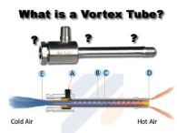
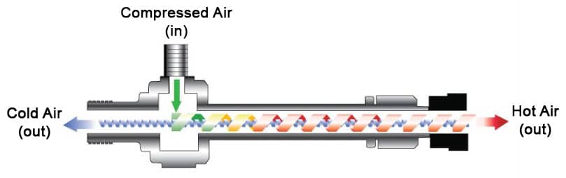
How does cold and hot air come from ONE compressed-air stream?
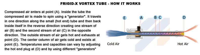
A fluid, such as water or air that rotates around an axis — like a tornado — is called a vortex. A Vortex Tube turns factory compressed air into two airstreams, one very cold and one hot, using no moving parts. It creates a tornado or vortex of compressed air that separates the fluid into two air streams: one hot and one cold. Vortex generator, which is a stationary and interchangeable part, regulates the volume of compressed air. The generator alters the airflows and temperature ranges.
The rotating air is forced down the inner walls of the hot tube at speeds reaching 1,000,000 rpm. At the Hot end of the tube, a small portion of this air exits through a hot air exhaust. The remaining air is forced back inside itself in the reverse direction through the center of the incoming air stream to create a stream of cold air at the cold end.The outside stream of air becomes hot and exhausts at the hot end of the tube. The heat of the slower-moving air directed at the cold end is shifted to the fast-moving incoming air, creating super-cooled air. The colder air flows through the center of the generator and exits through the cold air exhaust.
Different experimental methodologies have been used to confirm the flow behaviour inside a Vortex Tube and addresses the mechanism for the generation of cold and hot streams. “Energy analysis of flow properties in an air-operated Vortex Tube indicates that there is no outward energy transfer in the hot region of the Vortex Tube. The governing factor to determine temperature is attributed to the stagnation and mixture of flow structure.”
NOTE: The Vortex temperatures and capacities can vary by adjusting the hot end plug at the hot end of the tube and by using different generators.
The good news is that Vortex Tube behaviour is predictable and controllable. The Vortex Tubes have an adjustable valve at the hot end which controls the volume of the air flow and the temperature exiting at the cold end. By adjusting the valve, you control the “cold fraction”, which is the percentage of total input compressed air that exits the cold end of the Vortex Tube. Nex Flow’s Vortex Tubes may also be supplied with a fixed pre-set “cold fraction” instead of an adjustable valve.
The recommended guideline is: the less cold air released, the colder the air will become. The control knob adjusts the cold fraction, which is also a function of the type of vortex generator that is in the tube. There could be a high (industrial applications) or low cold fraction generator. A high cold fraction tube can result in 50-90°F (28-50°C) below the compressed air temperature. They also have greater air flow, yet they do not give the lowest possible temperatures. The maximum refrigeration capacity (greatest BTU/H or Kcal/H) results from a combination of airflow and cold temperature.A low cold fraction tube releases a smaller volume of air but extremely cold temperatures (down to -40°F/-40°C). Therefore, colder air is released with less volume. In summary, the maximum refrigeration (BTU/H or Kcal/H) capacity occurs with a higher cold fraction tube.
The hot air is vented to the atmosphere above the Vortex Tube through a muffler to reduce noise (optional). For Vortex Tube operated cabinet enclosure coolers (Panel Coolers), cold air in the control panel or cabinet is vented below the Vortex Tube. The cold air enters the panel through the cold distribution hose. Holes are punched into the hose kit to deliver the cold air evenly inside the panel where required. An optional muffler, in the cabinet, is added to reduce noise of exhausting air. Once sealed, the outside air is never allowed to enter the control panel.
How do you control the flow rate and temperature when using a Frigid-X® Vortex Tube?
The flow rate and temperature in a Vortex Tube are interdependent. To set the Vortex Tube to the desired temperature simply insert a thermometer at the cold end and adjust the hot end valve. The optimum cooling effect is achieved when the difference from the inlet air temperature and the cold air drops is 50oF (28 oC).
When using a Vortex tube in cooling laboratory samples or to test circuit boards, a ‘C’ generator is used because it limits the cold end flow rate to lower levels and produces very cold temperatures.
In summary, opening the adjustable hot end valve causes the cold air flow to decrease and the temperature drops. Closing the adjustable cold end valve increases the cold air flow and the temperature rises.
What are the advantages of the Vortex Tube compared to other cooling solutions?
Vortex Tubes have many advantages over other cooling solutions. They use no electricity and are safe since they have no explosive risk. They have no RF interference. They cool without refrigerants (CFCs/HCFCs) or moving parts for trouble free and reliable operation. Vortex Tubes are compact, lightweight, and easy to install especially in tight areas.
What is the Primary Application of Vortex Tubes?
The main function of a Vortex tube is to provide air conditioning for enclosures in an industrial environment. It provides cold, dry, and clean air to enclosures, which house sensitive instruments.
Nex Flow offers four types of “Packaged” Vortex Tubes: Frigid-X® Adjustable Spot Cooler is a low cost and maintenance free system that comes with a magnetic base for mounting. This type of vortex tube is generally used in a laboratory environment where temperature adjustment is needed. the units are portable and easily mounted. NOTE: If more cooling is the 30 SCFM (850 SLPM) generator is available for up to 2,100 Btu/hr. of cooling.
Frigid-X® Tool Cooleris designed for all types of dry machining applications for materials like plastic, glass, ceramic, titanium, and others such as aluminum (if not deep hole drilling), and it has been used for cooling needles in sewing and cutters for textile cutting. It can replace mist systems that are sometimes toxic when lubrication is not required. It is basically a no mess, no residue, and low-cost cooling solution. If some lubrication is required – a variation called Nex Flow® Sub-Zero Vortex® – can do just the job.
Frigid-X® Mini Spot Cooler is designed to cool small parts and produces a stream of 15 to 20 oF (minus -9.5 to -7 oC) of cold air to prevent heat buildup depending on inlet air temperature. It is often used to improve heat tolerances in machining of small critical parts and increase production rates.
Frigid-X® Box Cooler/Panel Cooler – For cooling small enclosures in laboratories, special environmental chambers, and various other application where an enclosure needs to be cooled.
Accessories
The following is a list of Nex Flow accessories sold with the Frigid-X® cooler products:
Hose Distribution kit to distribute the cold air inside the enclosure
Cold end muffler (Optional): The Cold End Muffling Kit consists of a silencer and all necessary fittings to connect to the Panel Cooler at the cold air outlet inside the electrical control panel. Depending on the capacity of the specific Panel Cooler, the dBA reduction offered by the Cold End Muffling Kit is 5 to 6 dBA. It is easy to install. Depending on the installation space available, it can be installed with a vertical or horizontal silencer.
Hot end muffler (Optional): The Hot End Muffling Kit consists of an ABS Plastic sleeve with silencing material fitted over the hot end of the Panel Cooler, outside of the control panel. The dBA reduction offered by the Hot End Muffling Kit is 2 dBA. It is also easy to install by fitting it over the top of the Panel Cooler. In addition to noise reduction, the hot end muffler offers additional protection from the hot end of the Panel Cooler.
Optional side mount is available for installing in tight spaces: Two sizes are available – one for coolers 8 SCFM and under capacity; the other for larger coolers. The slim design minimizes the space of the cooler when mounted on the side.
Solenoid valve
Thermostat
NOTE: The Side Mount is attached on the side of a cabinet but as near the top as possible so that the Panel Cooler can fit into the limited space they have. The hose distribution kit should be strung along the top of the inside of the panel with some holes to exhaust the cold air to avoid stratification of hot air at the top of the enclosure. Properly installed, the Nex Flow® Frigid-X® Panel Cooler with Side Mount can provide maintenance free air conditioning for your electrical and electronic controls.
What types of Enclosures can be Used with a Vortex Tube?
The first step is solving over-heating internal panel heating issue is to identify the correct enclosure. Nex Flow Frigid-X® Panel Coolers are approved by Underwriters Laboratory (ULC Component Recognized). Nex Flow can be installed in four types of UL listed NEMA rated electrical panel coolers:
NEMA Type 12 (IP 54) – This enclosure is for environments where no liquids (dripping or splashing) or corrosive material is present. Used for industrial use where the enclosure must keep dust away from electronics and protects equipment against ingress of solid foreign objects (falling dirt and circulating dust).
NEMA 3R (IP 14) – A weatherproof enclosure that is sealed, has gasketed raised lids, and quick release lockable latches. Used to protect electrical panels outdoors. The strong enclosure will not be damaged if ice forms on the outside of the enclosure. It protects equipment against the harmful effects on the equipment due to the ingress of water (rain, sleet, snow).
Patented NEMA Type 4-4X (IP 66)—This patented designed watertight enclosure provides personal protection against hazardous parts. Used to protect outdoor equipment and is splash resistant. It protects instruments from water (rain, sleet, snow, splashing water, and hose directed water). If ice forms on the outside of the enclosure, no damage will be sustained by the equipment inside. This enclosure provides additional protection against corrosion.
Patented NEMA Type 4-4X-316L (IP 66) –The 316L stainless steel sealed enclosure is oil-tight, spray resistant, and is used in wet environments. It provides protection against dust. Used in food service, pharmaceutical, and extremely corrosive environments where 303/304 stainless steel is not adequate.
When spot cooling with a Vortex Tube, it is good to have a small flexible hose connection at the cold end to direct the cold air to the spot being cooled. You need to keep the hose length as short as possible, preferable under 8 inches. Watch how to install a Vortex Tube below!
</span
Appendix A: Advantages of using Vortex Tubes Additional advantages of Vortex Tube usage includes:
Metal generators, which are interchangeable
Adjustable temperature range
High precision engineered
Smooth internal surface
All stainless-steel body with welded connections
No moving parts; maintenance free because driven by air not electricity
Low cost solution
Made of stainless-steel with a brass generator as a standard item; no cheap plastic
The generators control the air consumption and are easily interchangeable.
Quiet because of optional hot and cold mufflers available
Extension of tool life reducing downtime and tooling costs.
Portable: Strong magnet is useful for easy attachment to metal (Tool Cooling System)
Keeps out moisture and dirt in enclosure cooling applications
Appendix B: What are the main issues with other cooling solutions for Panel Cooling? Compressed air panel coolers are the best option because:
Water cooled heat exchangers use water which is not compatible with electrics. In addition, scale buildup can cause reduced effectiveness over time and downtime for 4 descaling.
Refrigerant CFC or HCFC Heat Exchangers are costlier with higher installation cost and lower life expectancy Installation requires a floor drain for condensate. Machine vibration can cause loss of refrigerant and component failure. Average replacement cost of a compressor can be High. Filters require monitoring and change to prevent 4 failures.
Appendix C: Additional Applications of Vortex Tubes The following is a list of applications for the Vortex Tube:
Cool CCTV Cameras
Cool Machine operations/tooling
Cool electronic and electrical controls
Set hot melt adhesives
Cool soldered parts
Cool gas samples
Cool heat seals
Cool enclosures that house sensitive electronics and protect them from corrosive or dirty environments.
Solder Cooling
Adjusting thermostats
Cool plastic machined parts
Set hot melt adhesives
Cool welding horns on ultrasonic
Cool molded plastics
Cool Electronic components
Cool heat shrink tubing
Improve dry machining applications
Does not use coolant
Cheaper solution
Tool Cooling Systems are used for machining plastics, titanium, glass, and ceramics, testing sensors, setting adhesives,
Sharpening Tools
Routing
Machining Plastics
Drill and Cutter Grinding
Milling, Drilling, Routing and Surface Grinding
Plunge and Form Grinding
Setting Hot Melt Adhesives
Laser Cutting
Tire and Rubber Grinding
Band Saw Blade Cooling
Chill Roll Nip Cooling
Mini Spot Cooler applications:
Solder Cooling
Adjusting thermostats
Cool plastic machined parts
Set hot melt adhesives
Cool welding horns on ultrasonic
Cool molded plastics
Cool Electronic components
Cool heat shrink tubing
Humidity and temperature control: Ideal in typically very hot environments
Keep the electrical panel clean
Cooling an industrial camera using a Vortex tube
Keep electronics free of condensation
Programmable controllers
System control cabinets
Motor control centers
Relay panels
NC/CNC machine controls
Computer panels
Modular Control Centers
Laser Housing Cooling
Electronic scale cooling
Modular control centers
Food Service Equipment controls
Computer and Server Labs
Environments where cooler panels are near Personnel
When noise reduction is required
Programmable controllers
Line Control cabinets
Cool laser housings
Electronic scales
Small panel coolers are ideal for inkjet markers, recorders, and other small control panel applications
Medium panel coolers can be installed on almost any other panel size and multiple units can be used on very large panels
Used for cooling housing that has wired and wireless communications equipment
“What does dBA mean when someone talks about noise levels?”
Compressed air exhaust produces noise whether from cylinders, solenoid valves, or from blow off nozzles. Air conditioning and cooling technology has become more advanced as individual, industrial, and manufacturing demands have increased at the same rate. The efficiency of a type of cooler is a primary concern, but so is the noise level. Different types of air conditioners emit different noise levels and are noisier as they age. It is important to understand how noise is measured and the strategies that can be used to reduce noise in your factory environment. This article describes Occupational Safety and Health Administration (OSHA), their recommended occupational noise limits, penalties for not complying, and products that are designed to reduce noise so that the factory environment can comply with OSHA recommendations.
What is Noise and How is it Measured?
Most of us live and work in loud environments. Without proper ear protection, this can lead to profound hearing loss, which affects the quality of life of us, our friends, and our family. Noise and vibration are both fluctuations in the pressure of air (or other media) which affect the human body. Vibrations that are detected by the human ear are classified as sound. We use the term ‘noise’ to indicate unwanted sound.
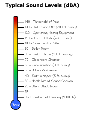
The logarithmic scale that measures sound and loudness is called a decibel.Sound energy travels in waves and is measured in frequency and amplitude. The intensity of the noise emitted from air conditioning units, for example, is the force of the sound wave (amplitude) and is measured in decibels (‘dB’). The decibel scalestarts 0, the softest sound a human can detect, and increases in multiples of 10 dB. Every increase of 3 dB represents a doubling of sound intensity or acoustic power. Table 1 lists the common sounds that are heard:
Table 1: Common Sounds
Sound
dBA
Breathing
10
Normal Speaking Voice
65
Rock concert
120
Dog Barking from 4 feet
95
Passenger car at 65 mph at 25 ft
77
Vacuum Cleaner
70
Noise levels is measured by a sound level meter using the decibel scale. The factors affecting the reading are:
The distance between the meter and the source of the measured sound
The direction the noise is facing relative to the meter
Is it an indoor or outdoor measurement? Outdoor sound will dissipate more than indoor noise, which reverberate.
For the sound measurement to be useful, the conditions under which the reading is taken and the distance from the source must be reported.
When purchasing a new air conditioner, the decibel noise level is printed on the specifications for indoor and outdoor units. If the decibel level is not on the specification, ask the installer to provide the measurement.
What is the difference between dB and dBA?
A dB(A) measurement has been adjusted to consider the varying sensitivity of the human ear to different frequencies of sound. Therefore, low and very high frequencies are given less weight than on the standard decibel scale. Many regulatory noise limits are specified in terms of dBA, based on the belief that dBA is better correlated with the relative risk of noise-induced hearing loss.
Compared with dB, A-weighted measurements underestimate the perceived loudness, annoyance factor, and stress-inducing capability of noises with low frequency components, especially at moderate and high volumes of noise. (Richard L St Pierre Jr and Daniel J Maguire, “The Impact of A-weighting Sound Pressure Level Measurements during the Evaluation of Noise Exposure” (paper presented at NOISE-CON, Baltimore, Maryland, July 12–14, 2004).)
db-C or the C-weighting scale is sometimes used for specifying peak or impact noise levels but there is generally not much of a difference between the two.
Occupational Safety and Health Administration (OSHA) Occupational Noise Exposure
Occupational Safety and Health Administration (OSHA) is an agency of the United States Department of Labour. Congress established the agency under the Occupational Safety and Health Act, which President Richard Nixon signed on December 29th, 1970.
OSHA sets legal limits on noise exposure in the workplace. These limits are based on the time a worker spends during a weighted average over an 8-hour day. With noise, OSHA’s permissible exposure limit (PEL) is 90 dBA for all workers for an 8-hour day. The OSHA standard uses a 5-dBA exchange rate.
The potential for a sound to damage hearing is proportional to its intensity, not its loudness. That is the reason why it is misleading to rely on our subjective perception of loudness as an indication of the risk to hearing.
Noise and vibration can harm workers when they occur at high levels or continue for a long time. The greater the sound pressure a sound has, the less time it takes for damage to occur to hearing. For example, an 85-dBA sound may take up to 8 hours to cause permanent damage, while a sound at 100 dBA can damage hearing after 30 minutes. Occupational exposure limits (OELs) for various noise levels are the maximum duration of exposure permitted. Table 2 lists decibel exposure time guidelines.
Table 2: Decibel Exposure Time Guidelines with Examples
Continuous dB
Examples
Permissible Exposed Time
85
Busy City Traffic
8 hours
88
4 hours
91
2 hours
94
Gas powered mower,
Hair dryer
1 hour
97
30 minutes
100
15 minutes
103
7.5 minutes
106
Tractor (105 dB)
< 4 minutes
109
< 2 minutes
112
< 1 minute
115
Leaf Blower, Rock Concert, Chainsaw
< 30 seconds
Table 3: illustrates the comparative noise level differences by 10 decibels
Noise Source
Decibel Level
Effect
Jet take-off (at 25 meters)
150
Eardrum rupture
Aircraft carrier deck
140
Military Jet Aircraft take-off from a carrier with afterburner (50 ft)
130
Painful. 32 times as loud as 70 dB
Steel mill auto horn at 1 m; live rock music
110
Average human pain threshold. 16 times as loud as 70 dB
Power lawn mower; Bell J-2A helicopter at 100 ft
100
8 times as loud as 70 dB. Serious damage possible in 8-hour exposure.
Motorcycle at 25 ft
90
4 times as loud as 70 dB. Likely damage in 8-hour exposure.
Dishwasher; Average factory, car wash at 20 ft; food blender
80
2 times as loud as 70 dB. Possible damage in 8-hour exposure.
TV audio
70
Upper 70s are annoying to some people
Conversation in a restaurant
60
Half as loud as 70 dB.
Conversation at home
50
One fourth as loud as 70 dB.
Library
40
One eight as loud as 70 dB.
Rural area
30
One sixteenth as loud as 70 dB
Whisper
20
Breathing
10
Barely audible
American Criteria
OSHA requires that workers exposed to an average of 90 decibels for eight hours wear hearing protection. Under the agency’s measurements, when the volume increases by 5 decibels, the nose doubles. As a result, the permissible exposure time is cut in half. If the levels reach 95 decibels, the maximum exposure without hearing protection is 4 hours.
The counsel for accreditation in occupational hearing conservation (CAOHC) has stricter guidelines. “Under the stricter guidelines, workers may not be exposed to 85 decibels for more than 8 hours a day without hearing protection. Several agencies have also concluded that the risk of hearing loss doubles with every 3 decibels increase, not 5.” (The New York Times, Retrieved on October 25, 2018)
Find out more about workplace safety and health topic with NIOSH here.
Canadian Criteria
The criterion level, often abbreviated as Lc, is the steady noise level permitted for a full eight-hour work shift. This is 85 dB(A) in most jurisdictions, but it is 90 dB(A) in Quebec and 87 dB(A) for organizations that follow the Canadian federal noise regulations.
The exchange rate is the amount by which the permitted sound level may increase if the exposure time is halved. The allowed maximum exposure time is calculated by using an exchange rate. As the sound level increases above the criterion level, Lc, the allowed exposure time must be decreased.
“In 2003, Directive 2003/10/EC of the European Parliament and of the Council on the minimum health and safety requirements regarding the exposure of workers to the risks arising from physical agents (noise) was adopted. This directive is to be transposed into the national legislation of all Member States before 15 February 2006 (132). The main characteristic of the new noise directive is to establish a clear and coherent prevention strategy capable of protecting the health and safety of workers exposed to noise.
Article 5(1) of the directive requires that, taking into account technical progress and the measures available to control the risk at source, ‘the risks arising from exposure to noise shall be eliminated at their source or reduced to a minimum’. In order to avoid irreversible damage to workers’ hearing, the directive foresees exposure limit values of 87 dB(A) and a peak sound pressure of 200 Pa, above which no worker may be exposed; the noise reaching the ear should, in fact, be kept below these exposure limit values. The directive also foresees upper and lower exposure action values of respectively 85 dB(A) (and 140 Pa) and 80 dB(A) (and 112 Pa), which determine when preventive measures are necessary to reduce the risks to workers. It is important to note that, when applying the exposure limit values, the determination of the worker’s effective exposure shall take account of the attenuation provided by the individual hearing protectors worn by the worker. The exposure action values shall not take account of the effect of any such protectors….
The directive also foresees detailed rules for the information and training of workers who are exposed to noise at work at or above the lower exposure action value.
Reinforced health surveillance is one of the main points of the directive: it confers, in particular, a right to the worker to have his/her hearing checked by a doctor or by another suitably qualified person under the responsibility of a doctor when the (132) Replacing Directive 86/188/EEC. 6.1. Noise in figures EUROPEAN AGENCY FOR SAFETY AND HEALTH AT WORK 99 upper exposure action values are exceeded. Preventive audiometric testing shall also be available for workers whose exposure exceeds the lower exposure action values, where the assessment and measurement of the noise exposure level indicate a risk to health.” (European Agency for Safety and Health at Work, Risk Observatory, Thematic Report 2, Noise in figures, Retrieved on October 25, 2018)
The new Noise Directive 2003/10/EC therefore reduces the exposure limit value from 90 dB(A), as set up in 1986 directive, to 87 dB(A), which represents clear progress.
Britain HSE allows users to calculate their daily doses of noise.
What are the Negative Effects of Noise?
Hearing loss can be categorized by which part of the auditory system is affected. There are 3 basic types of hearing loss: sensorineural, conductive and mixed
Sensorineural Hearing Loss – occurs when there is damage to the inner ear (cochlea) or hearing nerve in the brain.
Conductive Hearing Loss – occurs when sound is not conducted efficiently through the ear canal, eardrum or middle ear.
Mixed Hearing Loss – occurs when there is a combination of both sensorineural and conductive issues. In other words, both the middle ear and inner ear are affected.
Some causes of sensorineural hearing loss include:
Aging – gradual age-related hearing loss is called presbycusis
Excessive exposure to loud noise
Viral or bacterial infections
Certain Medications
Meniere’s Disease
Acoustic Neuroma a tumor which is located between the ear and the brain
Hereditary factors
Infection of the ear canal or middle ear
Fluid in the middle ear
Perforation or scarring of the eardrum
Wax build-up
Dislocation of the ossicles (three middle-ear bones)
Foreign objects in the ear canal
Otosclerosis
Unusual growths, tumors
Excessive exposure to loud noise can be caused by a one-time or by repeated exposure to loud sounds or sound pressure over an extended period. Sound pressure is measured in decibels (dB). If a sound reaches 85 dB or stronger, it can cause permanent damage to your hearing. With extended exposure, noises that reach a decibel level of 85 can cause permanent damage to the hair cells in the inner ear, leading to hearing loss. Damage happens to the microscopic hair cells found inside the cochlea. These cells respond to mechanical sound vibrations by sending an electrical signal to the auditory nerve. The healthy human ear can hear frequencies ranging from 20Hz to 20,000 Hz. The high frequency area of the cochlea is often damaged by loud sound. Exposure to high levels of noise can lead to:
Hearing loss;
Tinnitus (ringing in the ear);
Stress;
Anxiety;
High blood pressure;
Gastrointestinal problems; and
Chronic fatigue.
Worker’s Rights and Penalties
Workers have the right to:
Working conditions that do not pose a risk of serious harm.
Receive information and training (in a language and vocabulary the worker understands) about workplace hazards, methods to prevent them, and the OSHA standards that apply to their workplace.
Review records of work-related injuries and illnesses.
File a complaint asking OSHA to inspect their workplace if they believe there is a serious hazard or that their employer is not following OSHA’s rules. OSHA will keep all identities confidential.
Exercise their rights under the law without retaliation, including reporting an injury or raising health and safety concerns with their employer or OSHA. If a worker has been retaliated against for using their rights, they must file a complaint with OSHA as soon as possible, but no later than 30 days.
“Last year, US business paid more than $1.5 million in penalties for not protecting workers from noise.” “…an estimated 242 million is spent annual on worker’ compensation for hearing loss disability.” (www.osha.gov/SLTC/noisehearingconservation/, retrieved on October 18, 2018).
When health care facilities violate the regulations of the Occupational Safety and Health Act of 1970, the consequences the owners face can range from citations to jail time. Typically, the inspections are not planned. If a violation is found, the inspector will give the employer a deadline for fixing it and will issue a citation. OSHA schedules inspections based on several federal, regional, and local administrative priorities, but it also conducts inspections based on whistle-blower complaints and referrals.
If an OSHA violation is not corrected, OSHA will give a minimum fine of $5 000. OSHA can fine an employer up to $7,000 per day for not fixing a violation. The maximum fine for a repeated violation is $70,000. When a serious accident occurs, fines are certain or possible imprisonment.
Below are the penalty amounts adjusted for inflation as of Jan. 2, 2018. (OSHA Memo, 1/3/2018)
Type of Violation
Penalty
Serious Other-Than-Serious Posting Requirements
$12,934 per violation
Failure to Abate
$12,934 per day beyond the abatement date
Willful or Repeated
$129,336 per violation
State Plan States
States that operate their own Occupational Safety and Health Plans are required to adopt maximum penalty levels that are at least as effective as Federal OSHA’s.
For More Assistance
OSHA offers a variety of options for employers looking for compliance assistance including on-site consultation, education programs for employers and workers. Yo su can contact their regional or area office nearest to you for additional information.
Canadian Penalties
“The legislation holds employers responsible to protect employee health and safety. Enforcement is carried out by inspectors from the government department responsible for health and safety in each jurisdiction. In some serious cases, charges may also be laid by police or crown attorneys under Section 217.1 of the Canada Criminal Code (also known as “Bill C-45”). This section imposes a legal duty on employers and those who direct work to take reasonable measures to protect employees and public safety. If this duty is “wantonly” or recklessly disregarded and bodily harm or death results, an organization or individual could be charged with criminal negligence.” (OH&S Legislation in Canada – Basic Responsibilities, retrieved on October 25, 2018)
European Penalties
Penalties can include the following:
Fixed fines
On-the-spot fines
Remedial orders
Probation for companies and directors
“Might be used to underpin health and safety requirements – perhaps so-called ‘paperwork’ requirements: risk assessments, employee consultation arrangements, provisions for safety reps, compulsory insurance possibly, business registration, welfare provisions, and perhaps RIDDOR requirements.
If used in conjunction with improvement notices, fixed penalties might have the effect of helping to change duty-holder behaviour – since, in the absence of a new approach, prosecution is rare in these areas.
For use by enforcing authorities to relieve judicial system”
Alternative penalties including:
“Penalties used instead of, or in conjunction with, criminal prosecution for breaches of health and safety law serious enough to warrant consideration of criminal prosecution, and which, in addition to a punitive and deterrent purpose, might also have a restorative or restitutive element. At present, such penalties are either not available within the health and safety system or are not used.
Such alternatives to prosecution would need:
to fit the purpose of enforcement – that is, be effective in changing the behaviour of duty-holders and achieving improvements in health and safety outcomes, and
to satisfy the principles underpinning the Health and Safety Commission’s (HSC) Enforcement Policy: proportionality, targeting, consistency and transparency.”
Here at Nex Flow, we take noise levels into consideration very seriously because we understand that reducing noise levels from very loud and damaging compressed air equipment is important. Compressed air technology is used for cooling or blow off applications. Properly engineered air nozzles and air amplifiers can reduce noise levels by 10 dBA and air knives can operate under 70 dBA for blow off applications.
Where compressed air is exhausted from exit ports, mufflers may be added to reduce noise levels. The mufflers that perform optimally are ones with a Coandă profile used to entrain surrounding air along with the compressed air released, which converts pressure to flow. The conversion accomplishes three things: noise levels fall dramatically, energy consumption is reduced, and a laminar flow is maintained at a greater distance than from an open pipe, tube or hole so the nozzle or other blow off device is effective at a much greater distance.
Sound level is proportional to the velocity of the compressed air flow exhausted by a factor to the power of 8. . Sound Level ∞ Velocity 8 After mufflers are installed, the velocity can be reduced, which minimizes noise levels and also saves energy.
Conserve energy by turning off the compressed air tool when not in demand. This will also reduce noise in the workplace and save money.
Noise controls should reduce hazardous exposure to sound so that risk of hearing loss is eliminated or minimized. Not only will hearing loss be avoided, but communication between workers will improve. Air conditioning noise is unavoidable but investing in a new unit or noise absorbing equipment can reduce the noise output. Vortex Tube operated Cabinet Enclosure Coolers (Panel Coolers) operate under 80 dBA but have optional sound reducing packages to reduce noise levels to under 65 dBA. The noise measurement is typically taken about 3 feet from the source.
Modify, maintain, or replace aging equipment. Older air conditioners can collect dirt and other blocking materials over time. Best practices clean the air filters regularly. Internal parts, such as bearings of a fan motor, should be cleaned by a qualified technician. Fan motor bearings can also be adjusted to reduce noise. Vortex Tube operated Cabinet Enclosure Coolers (Panel Coolers) do not have these issues and offer advantages of near zero maintenance over traditional air conditioners for electrical and electronic cabinet enclosure cooling. They can be used in factory environments and only when compressed air is available for their operation. Other advantages they offer is no CFC’s or HCFC’s, keeping control panels at a slight positive pressure to keep out dirty environmental air, and no condensate. They maintain noise level consistently for years if the compressed air supplied is kept properly filtered.
Relocate noise-producing equipment (e.g., freezers, refrigerators, incubators and centrifuges) away from workers. Provide acoustic treatment for ceilings and walls. Controlling noise exposure through distance is often an effective, yet simple and inexpensive administrative control.
Note: Doubling the distance between the source of noise and the worker, the noise is decreased by 6 dBA.
Lower ceiling height to prevent sound from traveling and bouncing off surfaces, therefore amplifying noise.
Treat the noise source or the transmission path to reduce the noise level at the worker’s ear. Examples of inexpensive, effective engineering controls include:
Use low-noise tools and machinery
Maintain and lubricate machinery and equipment (e.g., oil bearings).
Place a barrier between the noise source and employee (e.g., sound walls or curtains).
Enclose or isolate the noise source.
Operating noisy machines during shifts when fewer people are exposed.
Limiting the amount of time, a person spends at a noise source.
Providing quiet areas where workers can gain relief from hazardous noise sources (e.g., construct a soundproof room where workers’ hearing can recover – depending upon their individual noise level and duration of exposure, and time spent in the quiet area).
Restricting worker presence to a suitable distance away from noisy equipment.
Have workers use hearing protection devices such as earmuffs, plugs
Whenever worker noise exposure is equal to or greater than 85 dBA for an 8-hour exposure or in the construction industry when exposures exceed 90 dBA for an 8-hour exposure, the employer is responsible for implementing a hearing conservation program:
Identify which employees are at risk from hazardous levels of noise.
Informing workers at risk from hazardous levels of noise exposure of the results of their noise monitoring.
Providing affected workers or their authorized representatives with an opportunity to observe any noise measurements conducted.
Maintaining a worker audiometric testing program (hearing tests) which is a professional evaluation of the health effects of noise upon individual worker’s hearing.
Implementing comprehensive hearing protection follow-up procedures for workers who show a loss of hearing (standard threshold shift) after completing baseline (first) and yearly audiometric testing.
Proper selection of hearing protection based upon individual fit and manufacturer’s quality testing indicating the likely protection that they will provide to a properly trained wearer.
Evaluate the hearing protectors’ attenuation and effectiveness for the specific workplace noise.
Training and information that ensures the workers are aware of the hazard from excessive noise exposures and how to properly use the protective equipment that has been provided.
Data management of and worker access to records regarding monitoring and noise sampling.
How does Nex Flow products reduce noise levels?
Compressed air exhaust air is a source of noise and why noise reducing products, such as air nozzles, air knives and air amplifiers are used in factories. To protect workers from excessive and damaging noise levels, the excess noise can be reduced up to 10 dBA.
The X-Stream® Sound Level Meter is used to measure and monitor the sound level in all types of industrial environments. The handheld accurate meter, which has data collection, is used to identify noise problem areas that may be intermittent. It is used for compressed air exhaust noise measurement and identifies where costly and inefficient blow off can be replaced by energy efficient Nex Flow®blow off products.
Nex Flow manufactures specialized compressed air solutions that are easy to install and reliable. All products offer noise reduction in factories to enhance the safety of your environments. Nex Flow manufacturers high quality, economical, specialized compressed air solutions for blow, off, cooling, drying, and moving with representatives worldwide. Choosing Nex Flow means that you obtain the best customized solution, including full technical support. Our customer technical support provides blowing angle and direction tips during installation. All compressed air products have a five-year warranty against manufacturer’s defects.
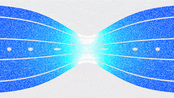
A Venturi System reduces pressure when a fluid flows through a constricted section (or choke) of a pipe. In 1797, Giovanni Battista Venturi performed experiments on flow in a cone-shaped tube and built the first flowmeter for closed pipes called the “Venturi tube”. A Venturi vacuum is created by a pump with compressed air running through it, yet the pump has no moving parts. Compressed air runs through the initial chamber, then a smaller portal that opens into another larger chamber, which is like the first one.
The static pressure in the first measuring tube (1) is higher than at the second (2), and the fluid speed at “1” is lower than at “2”, because the cross-sectional area at “1” is greater than at “2”.https://en.wikipedia.org/wiki/Venturi_effect
Constricting a pipe where fluid flows through results in lower pressure. This principle is counter intuitive to common sense. Why does the pressure decrease? Where does the fluid go if the pathway is constricted? When fluid starts to flow, its velocity around the orifice in the pipe increases significantly because of the restriction in the cross-section. An illustration of this is water flowing through a pipe. Water is a liquid that is not easily compressed. When the water flows through the constricted region of a pipe, the water flows faster. The same volume of water must pass through the same space quicker. The smaller the constricted region of the pipe is compared to the original radius, the faster the speed of the fluid.
The faster the moving fluid, the lower the pressure (i.e. Bernoulie’s principle) and the higher the velocity, the greater the difference in differential pressure measured. Abrupt restrictions generate severe turbulence in a fluid. Adding a nozzle that are suited for higher flow velocities to fluids with abrasive particles will reduce turbulence and creates less pressure loss. Turbulence reduction is greater with Venturi nozzles and tubes where the restriction is created by longer, conical constrictions in the pipe wall.
NOTE: The longer the exhaust section of the pipe, the stronger the vacuum effect.
All Venturi systems, including gauges, meters, nozzles, orifice plates, chokes, and pipes can be supplied with different restriction diameter sizes so that the pressure loss and differential pressure generated can be optimized for the process conditions and applications. “In fluid dynamics, an incompressible fluid’s velocity must increase as it passes through a constriction in accord with the principle of mass continuity, while its static pressure must decrease in accord with the principle of conservation of mechanical energy” (Wikipedia, Venturi effect,Retrieved on September 18, 2018). Therefore, any gain in fluid kinetic energy and velocity as it flows through a restriction is balanced by a drop-in pressure.
Interesting note: The mass flow rate for a compressible fluid will increase with increased upstream pressure, which will increase the density of the fluid through the constriction (though the velocity will remain constant). This is the principle of operation of a de Laval nozzle. Increasing source temperature will also increase the local sonic velocity, thus allowing for increased mass flow rate but only if the nozzle area is also increased to compensate for the resulting decrease in density.
The Venturi system increases the sucking capacity of any air compressor. To configure a Venturi Vacuum, plug the compressor into one end, move the switch to the vacuum setting, and plug the other end into a vacuum device.
The main component is a Venturi tube. As fluid flows through a length of pipe of changing diameter. To avoid undue aerodynamic drag, a Venturi tube typically has an entry cone of 30 degrees and an exit cone of 5 degrees. (Wikipedia, Retrieved September 18, 2018).
Accessories
Quick disconnect/connect nozzle fitting
Pressure or vacuum gauges to monitor how much vacuum is created with the system
Vacuum pump to collect material and then use the Venturi system to move the material a greater distance
Advantages of a Venturi Vacuum System
The best advantages of a Venturi Vacuum System is that it:
Creates a high vacuum and amplified flow to generate a strong conveying force to move any material with ease.
Reduces energy costs with less air consumption and uses less pressure.
Less likely to contaminate air flow because of the straight through design, which prevents clogging.
Lightweight and portable; Simple configuration, which is easier to manufacture and less expensive to purchase. Quickly and easily assembled and attaches to existing configuration. Has no valves and requires no filters.
Configurable: Standard, Threaded (NPT or BSP) or Flanged connection
Available in a wide choice of materials: Anodized/hard anodized Aluminum, 304/316L stainless steel, and Teflon. Built to last: materials are treated to ensure longevity in the product’s life cycle
Exceeds multi-stage pumps by 2 to7 times
No electrical or explosion hazard
Venturi System Applications
Venturi tubes are used in processes where permanent pressure loss is not tolerable and where maximum accuracy is needed in case of highly viscous liquids. It is also used in applications where they replace electrically powered vacuum pumps:
Gas venting
Moving metal parts in a machinery rough environment:
Hopper loading; Plastic pellets for injection molding
Trim Removal
Filling operations
Material Transfer
Sandblasting
Gas through a transmission line or scrubber: Moves wet and dry material or fluid through a pipe
Energy Transmission: Transporting solvents and chemicals, for example, oil and gas, steam
Convert a standard air compressor into a suction machine to secure products with a uniform suction to secure a base to a surface. Using an air compressor as a clamping force also prevents the need for holes on a work surface.
Measure the speed of a fluid, by measuring pressure changes at different segments of the device:
Measure fuel or combustion pressures in jet or rocket engines
Measure small and large flows of water and wastewater
In metrology (science of measurement) for gauges calibrated for differential pressures.
Water aspirators that produce a partial vacuum using the kinetic energy from the faucet water pressure
Connect your vacuum bag to make vacu-formed laminates
Vacuum forming operations for efficient industrial applications
Atomizers that disperse perfume or spray paint (i.e. from a spray gun).
A vacuum pump is a device, which was invented in 1650 by Otto von Guericke. It removes air and gas molecules from a sealed or confined space, which results in a partial vacuum. Sometimes vacuum pumps remove gas from an area, leaving a partial vacuum behind or remove water from one area to another, such as a sump pump does in a basement.
The performance of a vacuum pump is measured on the speed of the pump or the volume of flow at the inlet in volume per unit of time. The pumping rate fluctuates for each type of pump and the gas/liquid/fluid that it is used on. The number of molecules pumped out of the container per unit of time or throughput is another performance factor.
A vacuum’s suction is caused by a difference in air pressure. A fan driven by an electricity reduces the pressure inside the machine. Atmospheric pressure then pushes the air through the carpet and into the nozzle so that the dust is literally pushed into the bag.
The components of a vacuum pump are:
Suction: The higher the suction rating, the more powerful the cleaner.
Input Power: The power consumption is in watts. The rated input power does not indicate the effectiveness of the cleaner, only the amount of electricity it consumes
Output Power: The amount of input power is converted into airflow at the end of the cleaning hose. The airflow is often stated in airwatts (watts).
How does a Vacuum Pump Work?
A rotating shaft, in a sealed space, removes air and gas molecules. This action progressively decreases the air density within the enclosure resulting in a vacuum. As the pressure in the enclosure is reduced, it becomes more difficult to remove additional particles. The amount of energy produced by a vacuum pump depends on the volume of gas removed and the produced pressure difference between internal and external atmosphere.
The two technologies used by vacuum pumps are gas transfer or capture.
Transfer pumps allocate the thrust from the vacuum side to the exhaust side to accelerate the gas. They move the gas molecules by kinetic action or positive displacement:
Kinetic transfer pumps direct the gas towards the pump outlet using high speed blades or introduced gas pressure. Kinetic pumps do not typically have sealed containers but can achieve high compression ratios at low pressures.
Positive displacement transfer traps gas and moves it through the pump. They are often designed in multiple stages on a common drive shaft. The isolated volume is compressed to a smaller volume at a higher pressure and expelled to the atmosphere (or to the next pump). It is common for two transfer pumps to be used in series to provide a higher vacuum and flow rate. The expelled gas is above atmospheric pressure when the same number of gas molecules exit the pump as enter it. The compression ratio is the exhaust pressure at the outlet measured in relation to the lowest pressure obtained at the inlet.
Capture pumps capture the gas molecules on surfaces within the vacuum system. This pump works at lower flow rates than transfer pumps but can provide a very strong vacuum. Capture pumps operate using cryogenic condensation, ionic reaction, or chemical reaction and have no moving parts. They can generate an oil-free vacuum.
The mechanical vacuum pumps usually have an electrical motor as a power source, but can alternatively rely on an internal combustion engine, and draw air from a closed volume and release it to the atmosphere. The rotating-vane vacuum pump is the most popular of kind of mechanical pump. Individual rotors are placed around a shaft and spin at high velocities. Air is trapped and moved through the intake port and a vacuum is created behind it.
Types of Vacuum Pumps
Pumps can be considered either wet or dry pumps, depending on whether or not the gas is exposed to oil or water during pumping. Wet pump will use oil or water for lubrication and/or sealing and this fluid can contaminate the swept (pumped) gas. Dry pumps have no fluid. They have tight spaces between the rotating and static parts of the pump, use dry polymer (PTFE) seals, or a diaphragm to separate the pumping mechanism from the swept gas. Dry pumps reduce the risk of system contamination and oil disposal compared to wet pumps.
Note: Vacuum pumps are not easily converted from wet to dry by changing the pump’s style. The chamber and piping can be contaminated if wet. Therefore, all wet pumps must be thoroughly cleaned or replaced, otherwise they will contaminate the gas during operation.
Primary/Booster/Secondary
Name
Type of pump
Primary (Backing) pumps
Oil Sealed Rotary Vane Pump
Wet Positive Displacement
Liquid Ring Pump
Diaphragm Pump
Dry Positive Displacement
Scroll Pump
Booster Pumps
Roots Pump
Claw Pump
Screw Pump
Secondary Pump
Turbomolecular Pump
Dry Kinetic Transfer
Vapor Diffusion Pump
Wet Kinetic Transfer
Cryopump
Dry Entrapment
Sputter Ion Pump
Reasons to use a Vacuum Pump:
Provide a force
Collect dust
Remove active and reactive constituents
Remove trapped and dissolved gases
Decrease thermal transfer
Increase the “mean free path” of gas molecules so that the pressure becomes useful.
The mean free path is the distance a molecule travels before colliding with another molecule. A molecule could experience the following types of flow in a vacuum:
Viscous flow, turbulent: Tremendous random movement as the molecules try to move into any open space that may lead to a faster exit.
Viscous flow, laminar: After a few minutes, the rush of molecules to leave ends and they begin to move to an exit in an orderly fashion.
Molecular flow: The mean free path becomes longer inside the diameter of the pipe creating free flow of molecules. The gas molecules will more likely collide with the pipeline (container) walls than with another molecule. As the pressure drops the conductance also drops until the gas flow changes to molecular flow. Conductance is the measure of the mass of gas flowing at the average pressure per meter of the pipe length.
Advantages of a Vacuum Pump
Moves large volume of air/low vacuum
Converts pressure to flow (requires higher pressure to operate)
Collects dirt, dust, and debris
Saves energy
Durable
Vacuum Pump Applications
Medical processes, which require suction such as therapy or mass spectrometers
Chemical and pharmaceutical applications
Scientific analytical instruments that analyzes solid, gas, surface, liquid, and biological materials such as electron microscopy
Process industries to vent fumes, remove dust and dirt, power equipment, and trash compacting:
Sugar mills
Pulp & paper
Cement
Vacuum tubes
Electric lamps
Semiconductors
Glass coating
Gyroscopes in flight instruments are powered by a vacuum source in case of an electrical failure.
Treatment plants for sewage systems
Remove water from one area to another, such as a sump pump does in a basement.
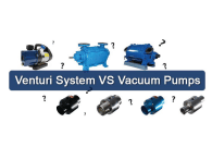
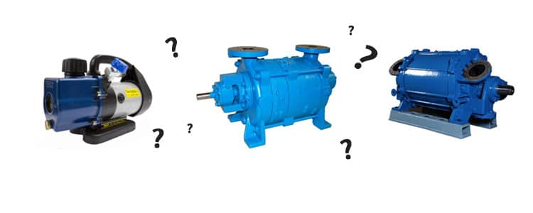
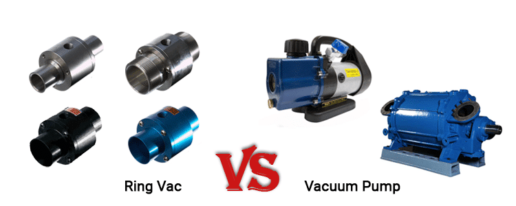
Venturi System VS Vacuum Pump
A Venturi system can be used in many of the same applications as a vacuum pump. The main advantage of Nex Flow’s Venturi system (Ring Vac) is that the units are compact and rugged, simple to configure and requires no maintenance compared to the vacuum pumps. When continuously venting air – choosing a low pressure vacuum pump can save energy costs. However – if intermittent conveying of materials is what you are looking for – a compressed air operated ring vac with an instant on/off switch can save energy cost when using compressed air.