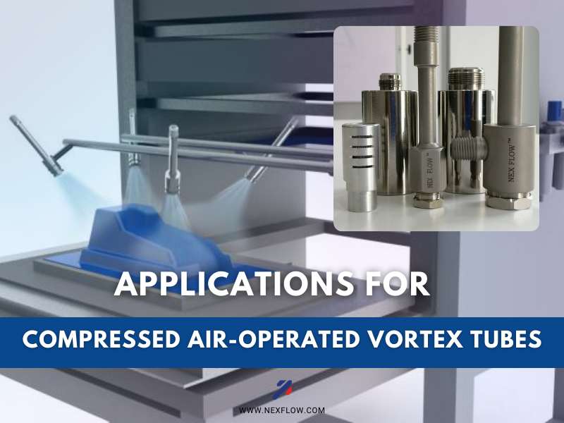
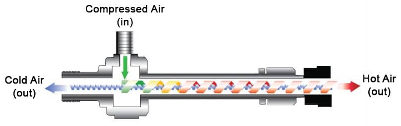
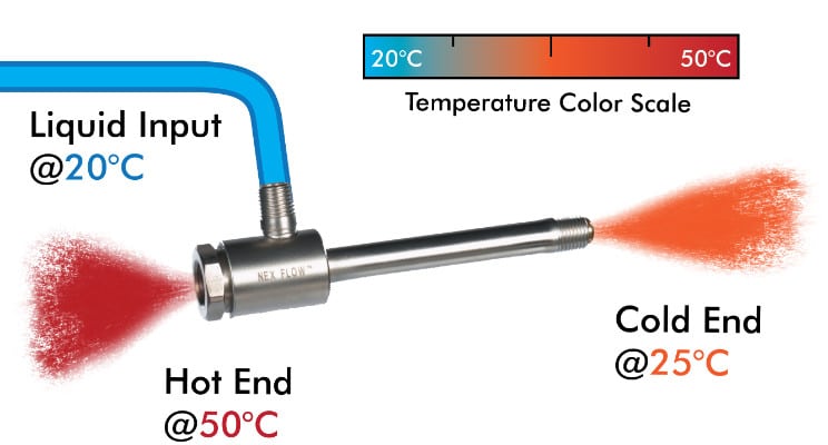
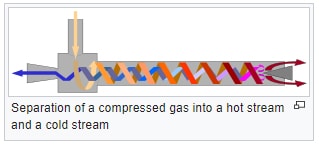
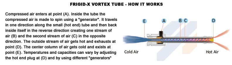
Applications for Compressed Air Operated Vortex Tubes. Compressed air-operated vortex tubes have been commercialized since 1960. These devices take compressed air at a given inlet temperature. And split the flow up into a hot (usually waste) and a very cold (usable) air stream used for cooling.
The significant temperature drop improves. When an application requires such low values, sub-zero temperatures can be produced. While the cost of compressed air is still a concern in their use, specific applications make them viable. Pay attention when these application advantages outweigh the energy costs.
Consider the following
Cooling CCTV cameras, sensors, small control boxes in inkjet printers, and other small devices with vortex tubes or packaged versions like Panel Coolers is more economical than using cooling water alone or compressed air alone. Some other alternatives can even be more costly or challenging.The cold air produced by the vortex tube means less compressed air is required to use only compressed air. Water causes scaling issues because of the high heat exposure and circulation through small water lines.
Fans to cool usually cannot work well because of the hot and often dirty environment. Using heat pipes requires a cool ambient to be effective and limits the ability to cool. A similar situation exists with thermoelectric cooling.
Cabinet Enclosure Cooling or Panel Cooling (Electrical and electronic air conditioners) is ideal for Panel Cooling under certain conditions over regular air conditioners, fans, and other alternatives like water and thermoelectric.Regular air conditioners generally use less energy, but you must address refrigerant replacement over time, change filters regularly, and deal with condensation. Vortex tube-operated coolers are dependent only on compressed air temperature for cooling effect.
As a general guide, the hotter and dirtier the environment, the greater the benefit of vortex tube technology. This is because the worse the environment, the higher the maintenance costs, especially filter replacement, which is not only a filter cost but can also be an ever-increasing disposal cost.
This can offset any increased energy costs.For obvious reasons, a dirty environment is not conducive to the use of fans. They will clog quickly and stop workingA hot environment aggravates the problem and works against using thermoelectric technology. Water cooling introduces potential scaling issues and other maintenance costs.
Vortex tube-operated panel coolers are essentially maintenance-free, produce no condensate to deal with, and keep the control panel under slight positive pressure to keep out any nasty factory environment.
This is very advantageous if maintenance is complex because of panel location, whether in a hard-to-reach factory location or in a geographical area that lacks the necessary maintenance personnel.
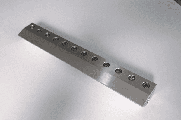
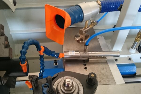
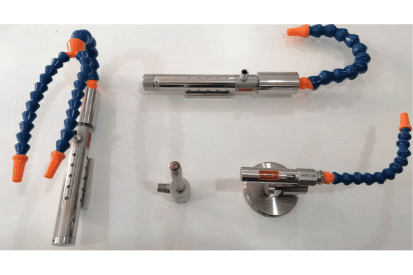
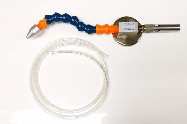
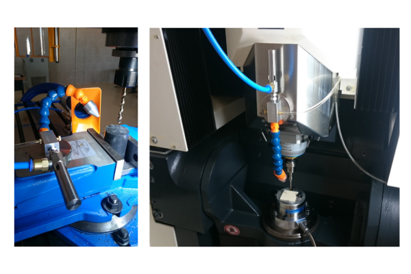
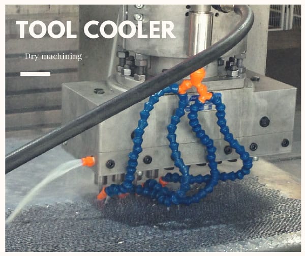
Manufacturers typically package vortex tubes with a magnet and flexible hose to direct cold air. Especially in dry machining applications involving ceramics, glass, plastic, and materials like titanium.This can decrease machine time and improve the quality of the machining.
There has been an attempt to move away from liquid cooling as much as possible for environmental and safety reasons, which continues today. However, there are challenges as liquid cooling helps remove debris, and tooling material requirements can also change.
Using vortex tubes to chill liquid used for mist cooing also provides some lubrication when needed, such as in deep-hole drilling, and reduces the lubricant needed by as much as 20%.
Vortex tubes are perfect for other spot cooling applications.. Such as cooling hot melt adhesives, welds, soldering points, and gas samples. Because of their compact design, small footprint, no maintenance, and low capital cost.
While the commonly available vortex tubes are similar in design. Which has not changed for decades, companies such as Nex Flow are developing new, more efficient versions. Providing the potential for greatly expanded use.
For assistance in using vortex tube technology, Nex Flow can help.
Air conditioners of various types utilized in the USA or Canada are required to meet certain safety standards with similar requirements in most other parts of the world. This is extremely important for industrial applications where they are used as enforcement but by authorities and within companies themselves is on an increasing trend.
Legal requirements governing the use of electrical equipment may sometimes appear complex, certain compliance requirements are clear and universally apply to electrical enclosure coolers.
The most important are the following:
OSHA and NEC Standards
The Occupational Safety and Health Administration (OSHA) governs safety and health in the American workplace and are used as a guide in many other countries many which have similar regulations. In 1971 the National Electric Code (NEC) was incorporated within the Construction Safety and Health Standards of OSHA and therefore all electrical equipment must also conforms to both the safety requirements of OSHA and the NEC. Vortex tube operated control panel air conditioners operate with compressed air. However, they often use electrically operated solenoid valves and thermostats, either as individual pieces or packaged together and these items themselves must meet these safety standards. If a solenoid valve for example is modified, it may be breaking a code. An example of this is drilling a hole in a solenoid to allow for some compressed air flow into an enclosure to keep it purged of environment air instead of using a separate air line for a bypass.
Local Authorities Having Jurisdiction
The Authority Having Jurisdiction (AHJ) that operates locally in the USA is responsible for enforcing local building codes and ensuring compliance. Many of the codes in force by the local authorities are based on the NEC, also known as the NFPA 70. However, others may add local addendums or use their own specific codes.
In all cases, before an installation can be energized the installation must be signed off by a local inspector mandated by the AHJ.
Increasing Importance of Nationally Recognized Testing Laboratories
To ensure that electrical equipment conforms to the relevant codes is to have the equipment certified by a Nationally Recognized Testing Laboratory (NRTL). This certification will be accepted by the AHJ. There are more than a dozen NRTLs licensed in the USA but the most well-known are UL (Underwriters Laboratory) and CSA (Canadian Standards Association).
Before selecting enclosure cooling equipment, make sure that the equipment has been certified and carries the NRTL certification mark. These testing laboratories do more than just “test”. They ensure that the materials used in the products meet a certain standard of quality. One issue with vortex cooler “knockoffs” for example is not only potentially poor quality, but also the use of below standard materials and parts that require a certain level of testing and approval. Anything below “standard” is risky with anything electrical or electronic.
Specific Canadian Requirements
Enclosure cooling systems sold in Canada must conform to the Canadian Electrical Code Part 1. The Canadian Standards Association (CSA) and certain other testing laboratories such as UL are accredited. There are some variations in test requirements and levels of acceptance between the USA and Canada to distinguish between American and Canadian certifications. UL for example puts a prefix C next to their mark and refers to both the USA and Canada approval. Sometimes both a C and US prefix and suffix is used to identify that the product is tested to the standards of both jurisdictions. It’s important to understand this difference so as to avoid the possibility of installing equipment with the incorrect certification for your region. CSA is based in Canada and again does the same with prefix or suffix identification to indicate approval for one or both jurisdictions. Nex Flow Panel Coolers have been tested and approved by UL to meet both Canadian and USA standards and bear the appropriate mark.
Hazardous Areas
Equipment designed for use in a hazardous area must also be certified as such. Your enclosure cooler must conform to the specific hazardous area rating applicable and must be compatible with the rating of the enclosure on which it is used. Proper wiring and connections should be particularly checked.
NEMA Type Enclosure Rating for the Enclosure and Area
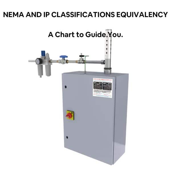
The enclosure cooling system used must have the same or better NEMA Type enclosure rating than the electrical enclosure itself. These NEMA Type ratings indicate the design level of the enclosure and the cooling system. For example NEMA Type 4 enclosures are suitable for applications and environments where the panel is subject to wash down. The vortex cooler (or whatever cooking is used) needs to be same or better for that wash down environment. Europe uses IP ratings. Various sources can provide the IP rating that is equivalent to the North American NEMA Type rating. Vortex Coolers like the Nex Flow Panel Cooler have versions tested and approved for NEMA 12 (IP 54), NEMA 3R (IP 14) and NEMA 4-4X (IP 66) applications.
In the U.S. and Canada, it is mandatory for certain equipment to carry the mark of an approved testing laboratory, and an enclosure air conditioner is on the list. Verify before you buy and be safe by using properly certified parts and equipment.
Seven Ways to make your Compressed Air Blow off and Cooling More Efficient
The majority of compressed air is used for blow off and cooling despite the push for alternate technologies like blowers simply because it is still the most efficient to use in a given application, either because of inadequate pressure from blowers, space problems or high capital and maintenance costs.
This is the reality and which is why compressed air use continues to grow.
So how can you make your compressed air use more efficient for blow off and cooling?
Look at the compressor room – do you need to address the air supply system efficiency? Can you reduce air compressor unloaded times? A great deal of developments in air compressor technology itself can improve overall supply efficiency which in turn increases end use efficiency. Is it the correct size and type for your factory use? Setting the maximum compressed air pressure to a lower level without harming downstream pressure requirements also reduces costs. Every 10 PSIG pressure reduction saves approximately 5% in energy savings.
Fix leaks- but not just pipe leaks, leaks at worn connectors which should be replaced, stuck auto drains on filters, even unsealed connections to air nozzles, air tools and other compressed air operated equipment. Because leaks also lowers downstream and end use available pressure, just fixing any leaks can help reduce the maximum pressure settings at the air compressors.
Check pressure losses – while your factory main compressed air piping maybe adequately sized to minimize pressure loss to the point of use, all too often the connection from the main line to the point of use utilizes piping or hose that is simply too small causing excess pressure loss. This is also compounded with fittings that are too small for the air requirement aggravating pressure loss. It is too common to measure pressure at the main line of 100 PSIG and only three feet away have losses up to 30% simply because the line size from the main to the application was too small. Always check the air requirement (AND pressure requirement of the air nozzle, air knife, vortex tube, panel cooler or any other end use product and be sure that the connection line is of adequate size.
Proper filtration and dryness – when dealing with compressed air blow off and cooling, devices like engineered air nozzles and vortex tubes require clean and dry compressed air. Any dirt buildup over time and excessive moisture negatively affects performance and can even clog the products. Always use point of use filtration to remove any excess moisture and particulate. Inadequate filtration can not only effect the device, it can also impact the quality of the product where any blow off is used.
Consider on-off control – a huge advantage of compressed air is that it can be stored and used on demand. When not used, it remains stored and energy is not consumed. Utilizing sensors and solenoid valves or a system such as the Nex Flow® PLCFC can take advantage of this storage ability which can yield tremendous energy savings. Many production lines do not need to have the blow off and cooling constantly on.
Consider New Pulsing Technology – pulsing of compressed air not new and solenoid valves have been used for years to do this. The problem with solenoid valves is however the high wear and tear and therefore the cost to maintain them typically offsetting any energy savings. It is also not certain how much energy is saved as other factors come into play when pulsing occurs. However, pulsing provides scrubbing action to help clean surfaces and a “push” to move or loosen a target where necessary. New process valves have, and still are being developed for pulsing to overcome these maintenance costs and offer potential for improved cleaning with engineered nozzles and for energy saving when properly applied. has done some projects with pulsing so has experience needed when using new pulse technology and offers consulting services for this as well as other applications.
Stay informed on new technologies for blow off and cooling but beware of false claims – Nex Flow® and a few other companies do research and development to improve products for blow off, cooling and conveying. Many others just copy, (usually not very well) other’s work and sometimes even claim it as their own. To stay focused, Nex Flow® provides compressed air blow off, cooling and conveying products and stays away from things like spray nozzles. Rather than being a supplier of all things, we specialize and share deep knowledge and experience in what we actually know. This is evidenced by our history of success, continued growth and our unique patents of which there are more to come with ongoing R & D and innovation. Be very careful of product claims that make no sense of product performance, some which even defy the laws of physics. Make sure companies that offer blow off and cooling technology can even afford to get proper approvals where necessary such as for control Panel Cooling to be assured they will stay around to service you (and that the product is even legal!). Reliability, timely response, and quality product and service is always important.
With the advent of the Covid 19 pandemic, there has been an acceleration toward automation. Packaging solutions and advances have also become important. Pneumatics plays a very large part in both automation and packaging as outlined below in the blog
Part of pneumatic technology is the use of compressed air for blowing, moving and cooling. The rugged nature and general low cost of compressed air products for these applications as well as the extremely low level of maintenance required have become more important criteria where downtime and maintenance costs have also risen dramatically especially when compared to more complex and expensive capital cost alternatives.
Pneumatic and hydraulic systems have many similarities. Both pneumatics and hydraulics are applications of fluid power. They each use a pump as an actuator, are controlled by valves, and use fluids to transmit mechanical energy. The biggest difference between the two types of systems is the medium used and applications. Pneumatics use an easily compressible gas such as air or other sorts of suitable pure gas—while hydraulics uses relatively incompressible liquid media such as hydraulic or mineral oil, ethylene glycol, water, or high temperature fire-resistant fluids. Neither type of system is more popular than the other because their applications are specialized. This article will help you make a better choice for your application by describing the two types of systems, their applications, advantages, and disadvantages. The load or the force that you need to apply, the output speed, and energy costs determine the type of system you need for your application.
What is Pneumatics?
Pneumatics is a branch of engineering that makes use of pressurized gas or air to affect mechanical motion based on the working principles of fluid dynamics and pressure. The field of pneumatics has changed from small handheld devices to large machines that serve different functions. Pneumatic systems are commonly powered by compressed air or inert gases. The system consists of interconnected set of components including a gas compressor, transition lines, air tanks, hoses, standard cylinders, and gas (atmosphere). The compressed air is supplied by the compressor and transmitted through a series of hoses. The air flow is regulated by manual or automatic solenoid valves and the pneumatic cylinder transfers energy provided by the compressed gas to mechanical energy. A centrally located and electrically powered compressor powers cylinders, air motors, and other pneumatic devices. Pneumatic systems are controlled by a simple ON/OFF switch or valve.
Most industrial pneumatic applications use pressures of about 80 to 100 pounds per square inch (550 to 690 kPa). The compressed air is stored in receiver tanks before it is transmitted for use. The compressors ability to compress the gas is limited by the compression ratios.
Applications
Pneumatic systems are typically used in construction, robotics, food manufacturing and distribution, conveying of materials, medical applications (dentistry), pharmaceutical and biotech, mining, mills, in buildings, and tools in factories. Pneumatic systems are primarily used for shock absorption applications because gas is compressible and allows the equipment to be less susceptible to shock damage.
Applications of pneumatic systems include:
Air compressors
Vacuum pumps
Compressed-air engines and vehicles
HVAC control systems
Conveyor systems in pharmaceutical and food industries
Pressure sensor, switch and pump
Precision drills used by dentists
Air brakes used by buses, trucks, and trains
Tampers used to pack down dirt and gravel
Nail guns
High pressure bank’s drive-teller tubes
Manufacturing and assembly lines
Pneumatic motor, tire, and tools
Advantages and Disadvantages of Pneumatics
Pneumatic systems are selected above hydraulic systems because of the lower cost, flexibility, and higher safety levels of the system. Pneumatic systems are best suited for applications which require no risk of contamination because they offer a very clean environment for such industries as biotech, dentistry, pharmaceutical, and food suppliers. Since they use clean, dry, compressed air, the system can quickly convey items. The straight and simple design prevents clogging and reduces maintenance. Pneumatic systems are easy to install and portable. They are reliable and has an initial low setup cost because they operate on comparatively low pressure and inexpensive components that reduces operation costs.
No container is required to store the air that will be compressed because it is drawn from the surrounding atmosphere and filtered (optional). The entire system is designed using standard cylinders and other components. The air or gas used in a pneumatic system is typically dried and free of moisture so that it does not create issues to internal components.
Pneumatic systems provide rapid movement of cylinders because the air compressor flow rates. Air is very agile and can flow through pipes very easily and quickly with little resistance. Pneumatic systems are available in a wide variety in very small sizes. The pneumatic systems are clean and do not pollute because any exhaust is released into the atmosphere. The Pneumatic system is more agile because if the system needs to change directions, the simple design and control allows operators to update the system quickly without environmental impact.
Pneumatics are cheaper than hydraulic systems because air is inexpensive, plentiful, easy to obtain, and store. Pneumatic systems generally have long operating lives and require little maintenance because gas is compressible, and the equipment is less subject to shock damage. Unlike hydraulic systems that use liquids that transfers force, gas absorbs excessive force.
Safety is an important advantage of choosing Pneumatic systems. Since Pneumatic systems run on compressed air, there is very little chance of fire compared with explosion or fire hazard of using compressed hydraulic oil. It is also maintenance free since there is little need to replace filters.
It is essential to determine the amount of force required for your application because not as much force is created with pneumatic systems as with hydraulic systems. Pneumatic systems do not offer the same potential force as hydraulic systems so they should not be used for applications that require lifting or moving heavy loads. Compressed air experiences air pressure fluctuations, so that movement can be jerky or spongy at times while moving or lifting loads. A larger cylinder is needed to produce the same force that a hydraulic ram can produce. In terms of energy costs, pneumatic systems cost more than hydraulics because the amount of energy lost through heat produced while compressing air. Another significant concern about pneumatic systems is the noise that is created. If used, it is the responsibility of the owners to protect their workers from hearing loss.
What is Hydraulics?
Hydraulics is used for the generation, control, and transmission of power using pressurized liquids. It is a technology and applied science involving mechanical properties and use of liquids. Hydraulic systems require a pump and, like pneumatic systems, uses valves to control the force and velocity of the actuators. Industrial applications of hydraulics use 1 000 to 5 000 psi or more than 10 000 psi for specialized application. The word hydraulics originates from Greek words hydor – water and aulos – pipe. The following equipment is required for a hydraulic system: hydraulic fluid, cylinder, piston, pumps, and valves that control the direction of flow, which is always in one direction.
Hydraulic systems, unlike Pneumatic systems are often large and complex. The system requires more room because a container is required to hold fluid that flows through the system. Since the size of the system is larger, it requires more pressure; making it more expensive than Pneumatic systems. Due to their overall larger size and the incompressibility of oil, hydraulic systems can lift and move larger materials. Hydraulic systems are slower because oil is viscous and requires more energy to move through pipes. During configuration and planning, if the factory or plant has several hydraulic machines, it is ideal to have a central power unit to reduce noise levels.
Applications
Due to the risk of potential hydraulic oil leaks from faulty valves, seals or hoses – hydraulic applications do not apply to anything that would be ingested – such as food and medical applications. They are used in a variety of everyday machine applications:
Elevators
Dams
Machine tools: hydraulic presses, hoppers, cylinders, and rams
Amusement parks
Turbines
Dump truck lift
Wheelchair lift
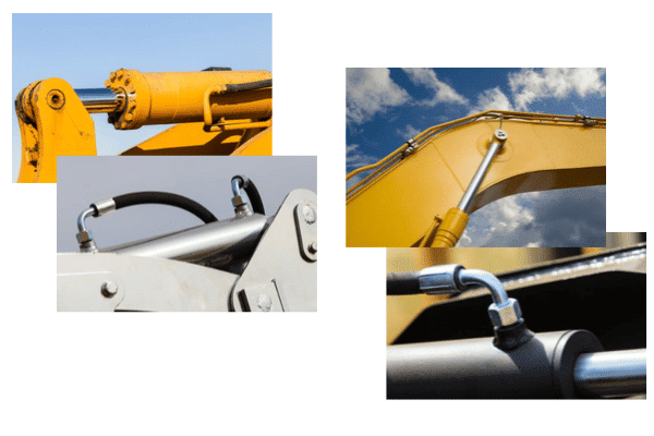
Excavating arms for diggers
Hydraulic presses for forging metal parts
Wing flaps on aircraft
Hydraulic braking system in cars
Lift cars using a hydraulic lift
Jaws of life
Advantages of Hydraulics
Hydraulic systems are more capable of moving heavier loads and providing higher forces due to the incompressibility of liquids. Hydraulic systems do many purposes at one time, including lubrication, cooling, and power transmission. Hydraulic powered machines operate at higher pressures (1 500 to 2 500 psi), generating higher force from small-scale actuators. To effectively use a hydraulic system, it is essential to pick an appropriately sized component to match the flow.
Hydraulic systems are larger and more complicated systems. Liquid, such as hydraulic oil is viscous and requires more energy to move. A tank is also required to store the oil from which the system can draw from when the oil is reduced. The initial costs are higher than Pneumatic systems because it requires power that needs to be incorporated into the machine.
Any leaks in a hydraulic system can cause serious problems. This system cannot be used for food applications due to high risk of hydraulic oil leaks from faulty seals, valves, or burst hoses. Appropriate plumbing procedures, preventative and regular maintenance, and having the correct materials on hand to minimize potential leaks and to quickly remedy any issues need to be in place at each site. In conclusion, pneumatic devices are best suited to execute low scale engineering and mechanical tasks while hydraulic systems are best for applications that require higher force and heavy lifting.
Summary: In general, it is a good rule of thumb to use hydraulic systems primarily for heavy lifting applications such as the jaws of life, elevators, hydraulic presses and arms in heavy equipment, and wing flaps for airplanes because these types of systems operate at higher pressures (1 500 to 2 500 psi), generating higher force from small-scale actuators. When it comes to moving or manufacturing products, especially food or pharmaceutical, it is recommended to use pneumatic systems because there is no chance of contamination due to burst pipes or oil leaks. Nex Flow Air Products Corporation manufactures compressed air products for blow off, industrial cooling (Vortex Tubes), air operated conveying, and air optimization designed to reduce energy costs while improving safety and increasing productivity in your factory and manufacturing environments.
Engineered air jets, air knives, air amplifiers, and air nozzles are examples of blow off products manufactured and sold by Nex Flow. They are safe because they meet OSHA noise and pressure requirements. Air Amplifiers are recommended for purging tanks, venting fumes, smoke, lightweight materials from automobiles, truck repair, or from other confined spaces. These products are also used to clean and dry parts, remove chips, and part ejection. They can also be used as effective tools for your manufacturing environment.
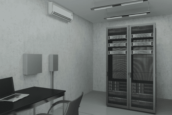
Vortex tube industrial cooling applications converts compressed air into very cold air for spot cooling. Nex Flow provides Vortex Tubes and Cabinet Enclosure Coolers. These products are ideal for use in high temperature and harsh environments. These products are especially ideal for use in high temperature and harsh environments. They also provide smaller vortex tube operated mini-coolers and vortex cooling for tool cooling systems. These systems can provide extremely cold temperatures without the use of refrigerants, such as CFCs or HCFCs. Industrial vortex tube powered cooling products are recommended for cooling gas samples, heat seals, data centers, electronic and electrical control instruments and environmental chambers.
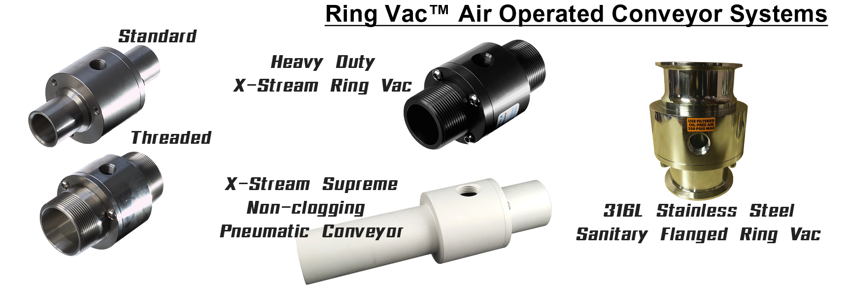
Compressed air operated pneumatic conveyors are designed to move materials at high rates and over long distances. They are ideal for continuous or intermittent use since they are operated by an on/off switch and controlled by a regulator. Our air operated conveyors are compact and have no moving parts. Nex Flow also provides fume and dust extractors, Ring Vac Operated conveyors and an X-StreamTM Hand Vac system. Air operated pneumatic conveyors are primarily used for conveying materials for applications where vacuum force is required to move objects over long distances at high speeds. These devices have an on/off switch to enhance safety. It uses compressed air, not electricity, so there is no explosion hazard. The Nex Flow Ring Vacs are made of anodized aluminum or stainless steel. They are designed to transport or vent a wide variety of lightweight products, raw materials, or fumes from one place to another in your factory. For high temperature and corrosive applications, regular and high temperature stainless steel is available. When moving food and pharmaceutical products, 316L Stainless Steel pneumatic conveyors are used. The specially design non-clogging model XSPC air operated conveyors are easy to install and use, compact and portable, and maintenance free.
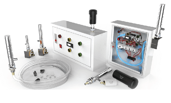
The systems offered by Nex Flow optimize compressed air system operations because of efficient design. The systems can be easily turned on and off so that the compressed air is used only when needed. The products do not have high maintenance costs and are light weight. System optimization can be achieved with the compact sound meter, ultrasonic leak detector and PLC flow control (PLCFC) system for compressed air, which uses photoelectric sensors to turn on the air when the target passes the sensor and to turn off the air when it leaves the sensor or can be set by time. This device can be used for dust and debris blow-off, part drying system, cooling hot parts, and cleaning parts before packaging. Nex Flow offers various accessories that are integrated into pneumatics systems to increase the efficiency of compressed air conveying products and systems. Some accessories include nozzles, mufflers, filters, mounting systems and static control for blow off of dust and debris from statically charged surfaces.
Nex Flow pneumatic products reduce noise, enhance factory safety, and provide excellent venting, cooling, and blow-off solutions. Compressed air conveying systems provides instant response times and are the most efficient and effective way to convert pressure into useful flow. The cost-effective pneumatic conveying systems provided by Nex Flow are simple, light weight, compact, reliable, and easy to install and use. Since there are no moving parts, pockets or angles to collect debris, moisture, or water, the maintenance costs are minimal. Expect the best from Nex Flow technicians, who are trained to help you determine the best solution for your application.
Industrial Panel Air Conditioning Options and Trends
The various options for cooling electrical cabinet coolers include, traditional compressor-based air conditioners, air-to-air heat exchangers (with heat pipes), thermoelectric air conditioners, and finally vortex coolers. Each cooling method has its plus’s and minus’s.
Sensitive electronic devices are used increasingly in hostile environments. High temperatures, contaminant-laden air, high humidity and corrosive atmospheres are bound to negatively affect sensitive electrical and electronic equipment. Damage to the controls can result in costly repairs, downtime, and even lost data. Inadequate protection of the controls can cause unwanted heat buildup, which can increase an enclosure’s internal temperature above the manufacturer’s recommended ratings for electronics/electrical equipment installed inside. This heat can come from both internal and external sources.
Internal heat sources come from the very components that needs cooling. These include:
Variable Frequency Drives (VFD’s)/inverters
Battery Pack back-up systems
Communication equipment
PLC systems
Power supplies
Routers & switches
Servers
Transformers
External heat sources come from the factory environment. Including:
Heat from blast furnaces and foundries in heavy steel and metals production
engine rooms
food processing factories with high humidity and heat
industrial ovens from bakeries and paint facilities
hot climates in general
manufacturing plants, especially producers of materials like insulation, carbon black or where other airborne dust and dirt particles are in the factory atmosphere
outdoor solar heat gain if the control are in direct sunlight
uninsulated and/or non-air conditioned buildings that heat up during the day
Although these heat sources may present a problem and potential damage to the systems – there are various methods in keeping the control panel cool. Here are some ways along with their advantages and drawbacks. Traditional Compressor-Based Air Conditioners Pros: High cooling capacity Cons: Higher maintenance, high capital cost, more sensitive to breakdown the worse the environment
Compressor-Based air conditioners rely on chemical refrigerants to remove heat from electronic/electrical enclosures. In addition to refrigerants, these air conditioners also use compressors, evaporators, condensers, and fans to provide cooling. The refrigerants used in the past are being replaced with more environmentally friendly products but the cost of these new refrigerants are sometimes ten times that of the obsolete refrigerants. In addition, some if not most of these new refrigerants are flammable which means there are design changes to insure safety when connected to a control panel with a potential to produce a “spark”. These units produce condensate which must be removed. Fans need filters which must be cleaned or replaced. If mounted on equipment subject to vibration then the refrigerant can leak out prematurely and need costly replacement. This also means more shutdowns affecting production. Depending on the factory environment lifespan of a traditional air conditioner can be anywhere from five to ten years but in very harsh environments, much much less.
Air-to-Air Heat Exchangers Pros: Low maintenance, relatively inexpensive Cons: Cannot cool below ambient so limited by environment.
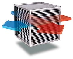
Efficient, cost-effective cooling can be realized through heat pipe assembly systems. These air-to-air heat exchangers remove waste heat from sealed electrical panels and enclosures to protect sensitive electronic components without exposing them to harsh, dirty environments outside the cabinet, a nice advantage. Simple design means long life as well, although because they use fans, the fans need to have care and maintenance, especially in harsh factory environments. However, the big problem is that you cannot cool below the environment ambient temperature and in many factory environment that temperature is still too high and therefore limiting the use of this technology.
Thermoelectric Air Conditioners Pros: Reliable, relatively low maintenance Cons: Cooling capacity is limited, and must be careful to size accurately, potentially use much more power to operate, extra care needed in installation. Thermoelectric solid-state air conditioners utilizing the Peltier effect were introduced some years ago but only have limited use for a variety of reasons. This effect is harnessed by using two elements of a semiconductor constructed from doped bismuth telluride. Upon application of a direct current (DC) power source, the device transfers heat from one side to the other. The side that heat is taken from becomes cold. They can dissipate loads up to 2,500 BTU/hr. However, there are some issues to consider. Peltier modules release a large amount of heat in the course of operation. They require in the cooler heatsinks and fans capable of efficiently deflecting surplus heat from the cooling modules. Thermoelectric modules are noted for their relatively low efficiency coefficient; when they act as heat pumps, they are powerful sources of heat. Using these modules in cooling devices however, intended to protect the electronic components of the computer, dramatically increases the temperature within the system unit. This sometimes requires additional cooling devices within the controls. If you don’t use additional cooling, the high temperatures can complicate operating conditions — even for the modules. Also, using Peltier modules creates a relatively heavy extra load for the power supply to handle. At the cooling side, the low temperatures produced by the operation of Peltier coolers can be too low and cause moisture from the air to condense inside the cabinet. This is dangerous for electric components. Therefore extra care needs to be taken in choosing the correct unit. When choosing a Peltier module of appropriate cooling power, it is necessary to ensure that the entire surface of its cold and hot sides are used. Otherwise, the parts of the module that do not have contact with the surface of the protected object (such as a processor chip) will only waste power and emit heat, decreasing overall cooling efficiency, possibly quite dramatically. One comment made by an informed user was that “They only become effective when the temperature differential is large enough. In most cases it will just increase the wattage drawn without doing anything that much better than a plain air conditioner.” The cold side gets cold, but then you’ve got an even larger amount of heat to remove from the hot side. So you need an even larger heatsink or some heat removal system on the other side. Hence the extra care in any installation.
Vortex Coolers Pros: Low maintenance, small footprint, low cost, keeps out moisture and dirt, no condensate, not subject to vibration, easy to install. Cons: Require compressed air
Vortex coolers can be a low cost way to cool and purge electronic/electrical enclosures, especially in situations where conventional cooling by enclosure air conditioners is not possible. Applications may include small to medium size equipment enclosures. Vortex coolers use compressed air to provide a cooling air flow. This means they are limited to applications where there is a ready source of clean, compressed air such as in medium to large industrial plants. The positive aspect is that it is these sizes of factories that usually have the cooling issues with their electrical and electronic control panels – hot and humid environment, and dirt and particulate in the atmosphere, have the compressed air.
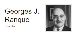
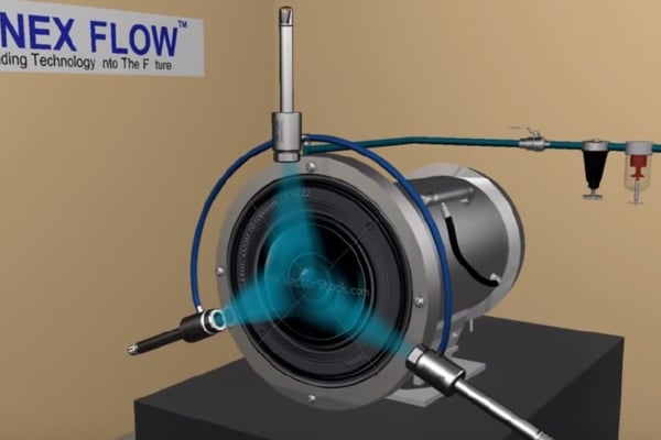
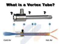
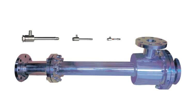
The primary component in a vortex cooler is a vortex tube, also known as the Ranque-Hilsch vortex tube that creates a swirling effect from the compressed air input and separates it into hot and cold air streams. A vortex cooler is unique in that it has no moving parts. At the end of the hot tube, a small portion of this air exits through a needle valve as hot air exhaust. The cold is pushed into the enclosure which air conditions the cabinet. A properly designed vortex cooler like the Nex Flow panel Cooler has a built-in exhaust so there is no need to vent the enclosure, and has been tested and NEMA (and/or IP) approved to insure no water can get inside a cabinet from the outside. This vortex provides a positive purge on the cabinet, which also helps to keep dirt, dust and debris out of the enclosure. There is no condensate to deal with. Because the compressed air is filtered to be clean and moisture removed (a necessary requirement with vortex coolers), even if the compressed air supply is saturated with moisture before the filter, there will be no moisture inside the cabinet because the compressed air goes back to near atmospheric pressure keeping the relative humidity of the cooling air low. One nice feature about the cooling effect of a vortex tube cooler that is often not noticed is that its cooling effect depends only on the temperature of the compressed air. So even if very hot environments, for example right next to a hot furnace, as long as the compressed air temperature is reasonable, it will cool very effectively. It is very difficult to install a vortex cooler badly. It is simply a matter of putting in a standard knockout hole on the control panel, installing the unit, adding a hose with punched holes (to distribute the cold air around the panel quickly), and then let it operate. An optional thermostat with solenoid can turn the air on and off as needed to conserve energy. A major application is for variable frequency drives (VFD’s) where the cooling is normally needed only on startup only so energy use is actually quite minimal and very cost effective. The harsher the factory environment, the more vortex coolers become economical as they do not break down in such environments nor do they have the extra maintenance the alternatives require.
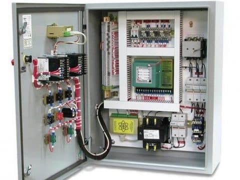
COMPRESOR BASED AIR CONDITIONERS
AIR-TO-AIR HEAT EXCHANGERS
THERMOELECTRIC AIR CONDITONERS
VORTEX COOLERS
INITIAL COST:
High and becoming Higher
Low
Moderate
Low
EASE OF INSTALLATION
Complex
Simple
Can be complex
Simple
ENERGY USE
Moderate
Low
Moderate
High
MAINTENANCE TIME & COST
Moderate to high
Moderate due to fans
Moderate
Low (may offset energy cost)
EASILY HELPS KEEP ENCLOSURE CLEAN
No
Yes
Yes
Yes
EASILY HELPS KEEP ENCLOSURE DRY
No
Yes
No
Yes
ABILITY TO COOL BELOW AMBIENT
Yes
No
Yes
Yes
FRIENDLY TO ENVIRONMENT
No (costly chemicals that eventually go Into environment)
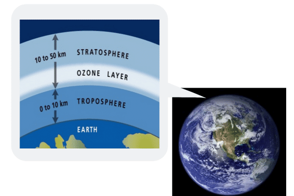
Air conditioners are everywhere, in homes, cars, office buildings, and even factories. They are also used to cool small enclosures, in particular electrical and electronic control panels. It is these small enclosures that this article will focus upon. Air conditioners utilizes refrigerant. The original refrigerants were CFC’s or Chlorofluorocarbons which are highly stable compounds that were also used as propellants in spray cans and in refrigeration and air conditioning units. Unfortunately, due to that stability they were found to deplete the ozone layer and were replaced by hydrochlorofluorocarbons (HCFCs). HCFCs and hydrofluorocarbons (HFCs) that came right after were created as substitutes for CFCs for use in refrigeration and a wide variety of manufacturing processes due to the lower effect on the ozone layer. HFCs have little effect on ozone but contribute to global warming. All of these classes of compounds either destroy the stratospheric ozone essential to life or contribute to global warming, international agreements have been signed to eliminate their production and use by the year 2040.
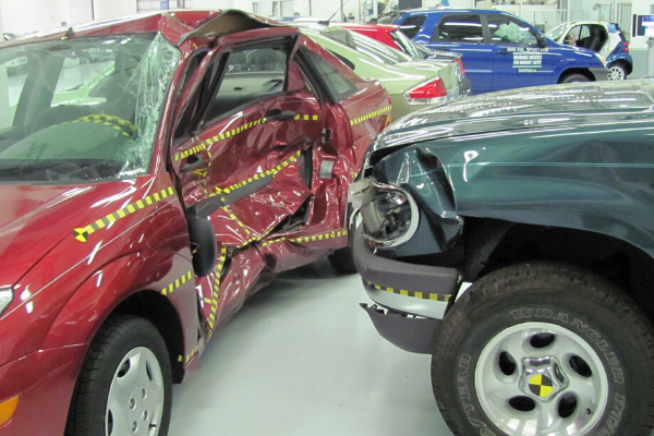
One of the problems with the new refrigerants is that most are flammable. For example, Flammable refrigerants are illegal to use in an automotive air conditioning systems. There are some exceptions, such as the new R1234yf refrigerant, which is mildly flammable but only under certain conditions. Before we focus on air conditioning of electrical and electronic control panels, let’s look at a major small enclosure use and that is in automobiles. Many automobile manufacturers have approved the product. However, it is notable that initially Daimler, the parent company of Mercedes-Benz originally did not approve the use of the refrigerant especially when a video that was made public of a test showed the interior of a Mercedes hatchback catching fire after R1234yf refrigerant leaked during a company test.
A thought to keep in mind is what happens if your vehicle is involved in an accident. The A/C condenser sits right in front of the radiator and contains high pressure refrigerant vapor and liquid. If the condenser is ruptured in a frontal collision (which it often is), high pressure flammable vapor will be released, almost guaranteeing an underhood fire! So presumably re-designs have been implemented to minimize any possibility of a fire in case of an accident. One possible solution to the flammability issue HFC-152a (or other flammable refrigerants) is to add a leak sensor inside the vehicle that warns the passengers if a leak occurs, and automatically opens the power windows to vent the vapors (thus, reducing the fire/explosion risk). Another solution is to redesign the A/C system so that it uses a “secondary loop” to keep the flammable refrigerant in the engine compartment and out of the passenger compartment. With this approach, the refrigerant circulates through an intermediate heat exchanger and chills a liquid (probably a water/antifreeze mixture) that then flows through the HVAC unit inside the vehicle. A recent report from the U.S. EPA says this approach meets its safety criteria, while also being energy efficient. But it does not reduce the risk of fire in a frontal collision, and it still poses a risk to technicians and do-it-yourselfers while recharging or servicing the A/C system. Honeywell developed in mid-2018 a product called Solstice N41 (provisional R-466A), a non-flammable and lower global-warming-potential (GWP) refrigerant for use in stationary air conditioning systems. Once on the market, Solstice N41 will be the lowest GWP, non-flammable, R-410A replacement refrigerant available worldwide. This is significant and would certainly address the flammability issue. But it still has global warming concerns albeit much less. Daimler and others such as Volkswagen also have opted to use CO2 as a refrigerant instead but CO2 requires high pressure systems and of course, CO2 is a greenhouse gas. But these alternatives do deal with the flammability issues.
After all this, there is a second problem with the new refrigerants – cost. The cost of the refrigerant itself is multiple times the cost of the old ones being replaced – as much or by a factor of ten times. Then there is a cost of material changes and some redesign of the air conditioners themselves.
Now, let’s change the environment to that of a factory floor in a production setting where air conditioners or cabinet coolers or panel coolers are used to cool electrical and electronic control cabinets. The first question is whether it is safe to have a flammable refrigerant used in a device that will be mounted to an electrical device? Design has to assure that a spark from a faulty control does not cause a fire from potentially leaking refrigerant. The second is cost, due to the high cost of these new refrigerants. Replacing refrigerant could be far more common on a plant floor compared to an automobile due to heavier use and also from vibration that the air conditioner may be subjected to. If the non-flammable refrigerant is used, or if a CO2 system is used, the cost is still much higher than traditional systems used in the past and cooling systems more complex.
What is certain, is the rising cost of traditional air conditioning systems. An alternative has existed for years and that is vortex tube cooling systems. These systems like the Nex Flow Panel Cooler use only compressed air to operate, with no carbon footprint, no flammability concerns, no chemicals to replace and virtually zero maintenance. Their use does require the facility to have compressed air but this is available in most large manufacturing plants. They are used mostly for control panel air conditioning in harsh environments where maintenance costs even on traditional air conditions offsetting the maintenance costs. With the new refrigerants coming into play, and with their extra costs for refrigerants, and most costly air conditioning assemblies, the very simple design of the vortex tube operated air conditioners become more economical. In addition new vortex tube panel cooler designs are being developed to improve their efficiency and more efficient air compressors are also being offered. So while at the traditional air conditioning end capital costs go up, the operating costs of vortex tube operated systems is trending downward.
Developments in new refrigerants should be carefully watched as it affects all of us concerning the environment and its impact of manufacturing operations and all other areas where they are used. But at least for manufacturing, there is a potentially better alternative with vortex tube operated systems like the Nex Flow Panel Cooler.
Electrical and electronic control panels are the heart of factory production. Any problems that occur with them can cause minor to major production hiccups, slow downs and potential need for a factory shut down. Just as you would take care of your own heart, it only makes sense that you recognize the heart of production and take good care of it.
But often this does not happen. How many times do you see control panel doors left open because they get “hot” inside. This creates a potential safety hazard and if the environment is not clean, it may cause dirt buildup inside the panels, on the controls – eventually leading to potential costly, premature failure.
As often as not, these control panels that are left open due to heat buildup is because of a lack of maintenance on whatever cooling system they may already have. It could be a simple external fans, external blowers, or traditional panel air conditioners. Even with water cooled systems, maintenance is necessary. External fans need filters, especially in dirty environments and these filters get dirty and require regular cleaning and/or replacement. Similarly with blowers, perhaps even more often. Water cooled systems have small water lines and can scale up, preventing adequate cooling. Traditional air conditions are an even more critical machines for regular maintenance. Not only do filters need to be cleaned and/or changed regularly, especially in dirty environments, if air conditioners are on machines that have vibration the refrigerant inside may leak out the unit. It is important to recognize the cost of the smallest downtime due to a control panel “going down”.
So what can be done? If whatever cooling system is working well and you do not have issues with control panels overheating, then of course nothing. Keep doing what you are doing. But if you have even once have to open a cabinet door to vent out some heat – then you have a problem. Would you ignore a sharp pain in your own heart? Well, that overheating is the panel’s pain.
One solution is to overhaul the maintenance program on the control panels as that can certainly be a source of the problem but that in itself may reveal and create other costs. But it is one option. Another option is to use a Nex Flow Panel Cooler.
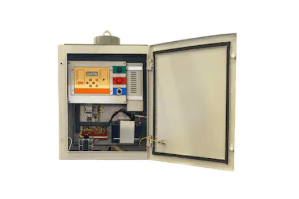
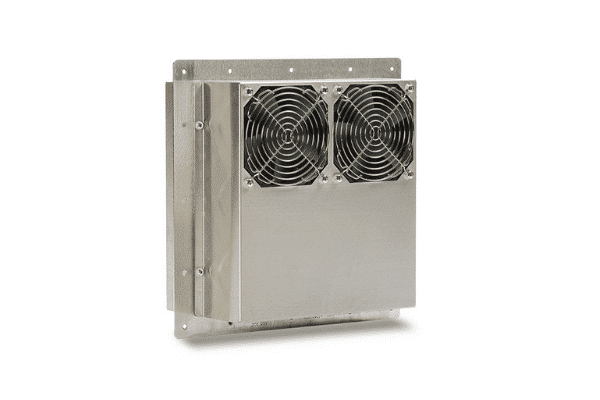
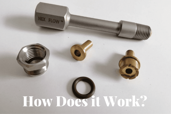
Despite the use of compressed air for operation the Nex Flow Panel Cooler is essentially maintenance free. Once installed, it can be left to operate under the worst conditions of a dirty factory environment, with high humidity, high ambient temperature and even on equipment that vibrates. How it works is simple – compressed air enters the Nex Flow Panel Cooler and the vortex tube component separates the compressed air into a hot and cold stream. The hot end is exhausted as waste but the cold air goes inside the control panel to cool and keep the cabinet from overheating. The connection to the cabinet has a built in exhaust to vent out the hot air displaced by the cold air. Since there are no moving parts, and no refrigerant chemical inside the unit, the Panel Cooler can handle equipment vibration. The air entering the cabinet keeps the cabinet at a slightly positive pressure keeping out any humidity and any dirt and particulate in the environment. The effectiveness of the air conditioning depends solely on the temperature of the compressed air and not the environment making Panel Coolers ideal to use in hot and humid locations. There is no condensate produced that needs to be disposed of and you do not have to worry about replacing filters. The only basic requirement is to properly filter the supplied compressed air. To conserve energy, a thermostat and solenoid valve control system can turn the air on and off as required. Alternatively an electronic thermostat system can be used. To keep the cabinet constantly at positive pressure to keep out a very nasty environment, a bypass system can be installed around the solenoid to always have a very small amount of compressed air flowing even when the unit is off.
If maintenance is not adequate or perhaps the environment is just so unfriendly it causes serious and costly issues for whatever the reason for problems with traditional air conditioning or other cooling systems, the Nex Flow Panel Cooler can be a viable option and the extra energy costs often offset by the shorter life span, or damage to controls and other problems created using other systems.
The Nex Flow Difference: Why we treat our materials differently?
Nex Flow Air Products Corp. sets itself apart from its competitors by doing a few things differently with the materials that we use in manufacturing our products. While some producers are actually quite similar in product as to how they deal with material, we stand out in four specific areas as to what we do with the materials of manufacture. Differences for Nex Flow are as follows:
Anodized aluminum parts
Powder coated parts
No Plastic in our vortex tubes
We do not mix aluminum and stainless steel in our vortex tube packages
Anodized Aluminum parts
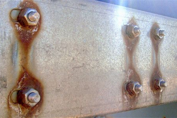
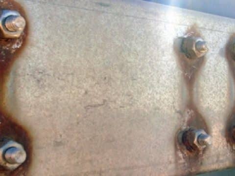
We make it a point to anodize our aluminum air knives, amplifier, air jets, air wipes and air operated conveyors. It is actually much easier (and certainly less costly) to produce these items without anodizing due to the importance of efficient aerodynamic design. When the products are anodized the surface changes, even if the change is very small, it makes it more difficult to keep a flat part flat (i.e. air knives). But, we CAN do and we do it because of the value the anodizing adds benefits to the products. Anodizing helps guard against the effects of the factory environment on the aluminum. Unprotected aluminum will form a powdering while oxide over time. Anodizing keeps the product looking better and longer even when using dissimilar metals in assembly, stainless shims, stainless screws, with aluminum bodies, it protects the accessories from even minor effects of cathodic corrosion. Cathodic corrosion can occur in a highly humid environment or if the parts get wet. Dissimilar metals can act like a battery where the more active metal can corrode unless there is some form of protection. You can see this effect, for example, with rust around screws used on some buildings or machines because the screws are of one material while the metal it is screwed into is another. When paint wears away, it leaves unprotected metal that is more electrically “active” than the metal in the screw. By anodizing and protecting our product, Nex Flow ensures that our accessories will last longer and look better over time.
Powder Coated parts
Some of our cast zinc parts, specifically our Air Edger flat jet nozzles and cast Fixed X-Stream Air Amplifier, also have powder coating. It provides a much better finish and look to the product and again, extra layer of protection from the factory environment. Powder coating is an excellent protection in a factory environment. Powder coating parts adds intrinsic value to the products to the betterment of the customer providing a product that is longer lasting look better through time.
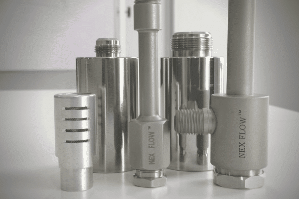
No Plastic in Vortex Tubes
Most manufacturers of vortex tubes use injection molded plastic “generators” which are used in the unit to initiate the compressed air spinning effect. Nex Flow machines their “brass” generators for that purpose instead of plastic. While plastic would be much less costly, brass offers a few advantages. Injection molding plastic will have some variations in production, especially as the mold wears out. By machining the metal generators we have much greater consistency with the parts which translates into much greater consistency in performance from one vortex tube to the next. Vortex tubes consist of several parts and of course, each part has a certain tolerance in manufacturing. Nex Flow has very tight tolerances on each part and the generators especially require very tight tolerances. The more pieces involved in assembling a part, the more the cumulative effect on the overall variation in tolerance and therefore performance since the operation of all Nex Flow products are based on aerodynamic shapes.
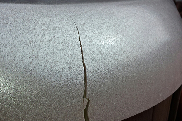
As the generator is such a critical component in a vortex tube, we recognize the need to use metal instead of plastic. Another advantage of using metal, in our case brass, instead of plastic is that plastic can possibly crack over time. If the compressed air supply is dirty the generator can also build up dirt and engrain itself, hence requiring replacement. The metal ones we use are easily cleaned. Sometimes vortex tubes or their packaged versions are used in very hot environments so the parts must be able to hold up in high temperature areas, especially when not operating. In these cases even competitive units replace their plastic generator with metal. Nex Flow vortex tubes and many of their packages are therefore more flexible in the environments where they can be used. While competitors would charge extra for a special product, our standard product can generally be used instead.
We do not mix Aluminum and Stainless Steel
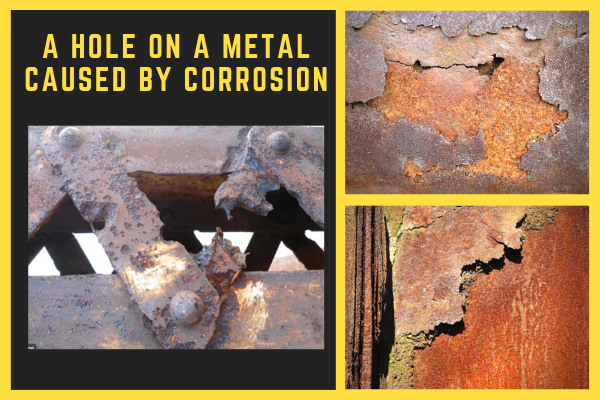
Our vortex tube packages include tool coolers, mini coolers, adjustable coolers, panel coolers, etc. Of particular importance is the materials used in a panel cooler used for cabinet enclosure cooling and camera cooling. Many manufacturers will use a stainless steel vortex tube packages as a control panel cooler using aluminum housing and attachments. While not a problem in relatively benevolent factory environments, it can become an issue in very humid area or in applications where they are used in wash down conditions. Cathodic corrosion can occur described earlier with dissimilar metals with air knives. On one visit to a customer there was actually a competitive vortex tube cooling system with a big hole on the side of the assembly. Cabinet cooling applications are very critical because you do not want any possibility for moisture getting into the control panel. This is the reason vortex coolers should have the proper approvals to insure this does not happen (such as Underwriters Laboratory testing and approval). Cabinet Coolers are essentially vortex tubes with a cover and some system to prevent moisture from getting inside of the cover and possibly then into the cabinet. This cover was aluminum and the vortex tube another material. The environment was a relatively wet environment, so over time cathodic corrosion cause the aluminum to corrode and create a hole in the protective cover. Thus, creating a potential risk for water to get into the electrical cabinet. It is for this very reason (preventing cathodic corrosion) that Nex Flow only has stainless steel covers for their stainless steel vortex tubes. Similarly with all other packages systems, whether they are tool coolers or adjustable coolers, the packages are made with stainless steel only and not a mixture of stainless steel and aluminum.
It’s a Wrap
These are some of the reasons why Nex Flow treats their materials differently. While some of these “differences” in material handling and treatment can be more costly from a manufacturing point of view, they do offer significant added value to the products and a benefit to the customer, and still with a very competitive price.
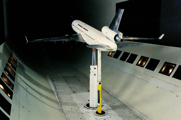
Wind tunnels are large tubes with air moving inside. These tunnels are used to test models of aircraft or other flying objects on their actions in flight. These models are scaled down versions of actual objects that will be built. Researchers and institutions around the world like NASA, uses wind tunnels to learn more about how an aircraft and spacecraft will fly. But it is not just flying machines that are tested. These Wind chambers are also used to test how an automobile shape, or windshield design will behave in environments with strong winds. Aerodynamics is the study of the flow of air or gases around an object in motion. Essentially these tunnels are hollow tubes with controllable fans at one end to test objects aerodynamics ensuring safety and performance of machines. Airplane builders use NASA wind tunnels to test new airplane designs. Credits: NASA
Frank H. Wenham (1824-1908), along with his colleague John Browning, invented the wind tunnel and built the first one in 1871. He described it as “a trunk 12 feet long and 18 inches square, to direct the current horizontally, and in parallel course.” As a British marine engineer he studied the problems of human flight and had many publications. He also made a huge influence in the development of aeronautics. Their experiments showed that high aspect ratio wings – long and narrow—had a better lift-to-drag ratio than short stubby wings with the same lifting area. Wenham may have been the first scientist to use/coined the word “aeroplane”. Aviation writer Carroll Gray says Wenham’s work may have been an important influence to the Wright brothers.
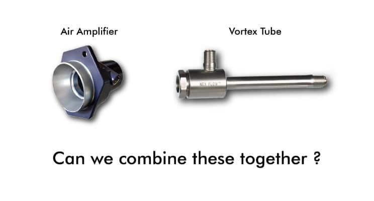
As mentioned above, wind tunnels typically use powerful fans. But – it is possible to use Nex Flow compressed air operated Air Amplifiers instead of fans for a miniature wind tunnel. To get the system to work, the gap setting on the Air Amplifiers will have to be increased to approach the power needed for testing even a very small object. Although there are limitations to using compressed air for wind tunnel emulation – they do offer some advantages like having a lower noise level and their ability to be combined with vortex tube technology for testing at sub-zero temperatures. Powerful fans overcome back pressure created by the length and overall volume in the tunnel. Compressed air amplifiers however cannot be “revved up” like a motor and are subject to this back pressure limiting the length and volume of a tunnel where it can be used. However for very light and small objects, it is conceivable to use an Air Amplifier to operate a miniature wind tunnel. Air Amplifiers take compressed air that is consumed and converts the pressure normally lost as pressure drop and noise into high velocity and high laminar flow. With fans you can control this velocity and flow by making the fan turn faster or slower. With Air Amplifiers you have some limited control with input pressure but in a much more narrow range which should suffice for a small miniature tunnel. A common setup at exhibitions is to attach an Air Amplifier to a stand and have the amplified airflow support a beach ball which can be held a few feet above the vertically aimed Amplifier. The object tested in an Air Amplifier operated miniature wind tunnel would have to be in the low weight range of a beach ball to be useful. A powerful compressed air operated engineered nozzle, or a series of engineered air nozzles might be paced at one end of a miniature wind tunnel for more force. After a short distance, the combined airflow could produce enough velocity and flow to be useful for testing small, light objects. One advantage of both using compressed air amplifiers or laminar nozzle is the lower noise level than you would get from a powerful fan.
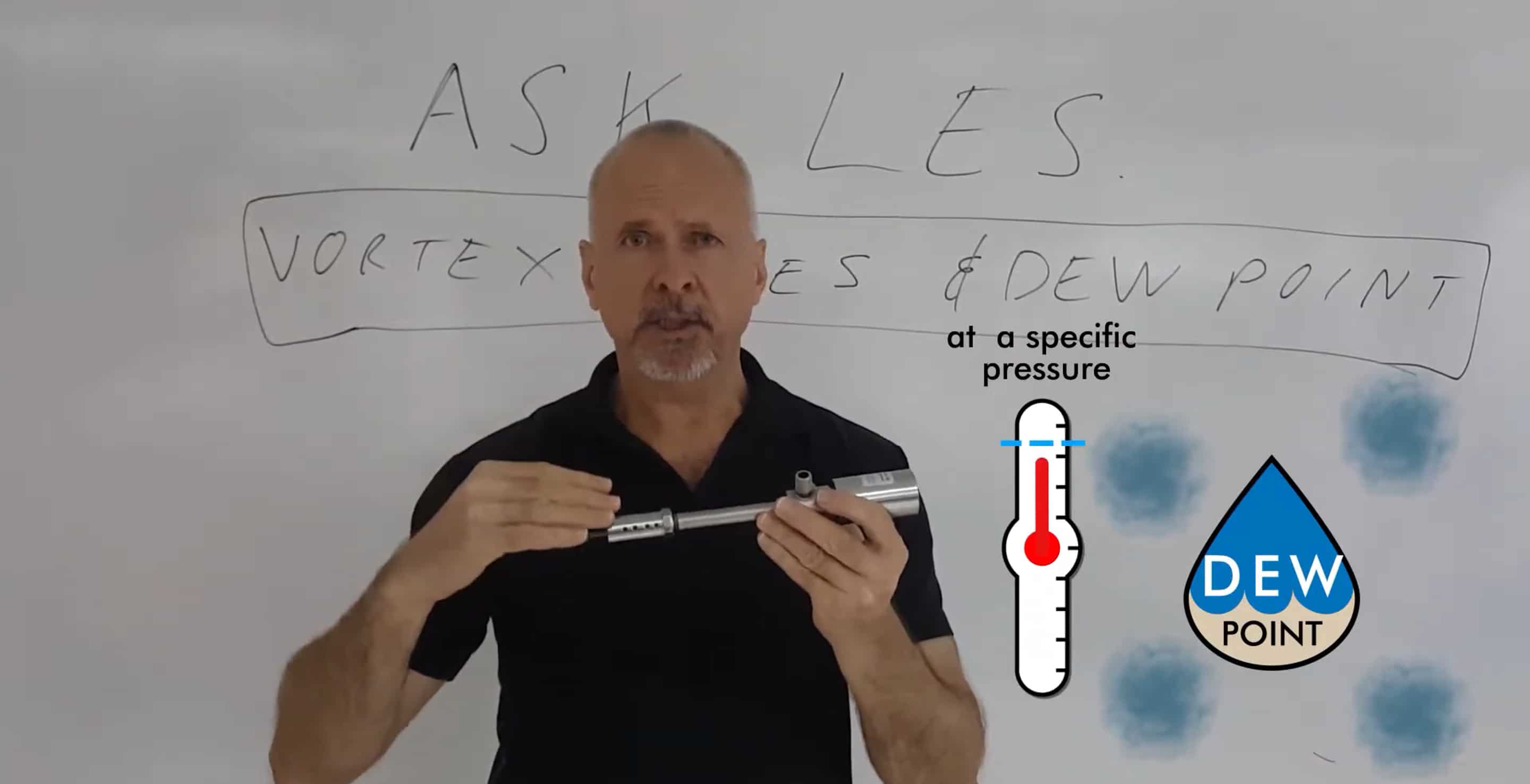
Vortex tube technology however, does offer one advantage for a special type of wind tunnel. A vortex tube is a device which takes compressed air and divides it up into a hot and cold stream. This cold stream of air flow can go to very low, sub-zero temperatures. Vortex tube commercially are available in air consumption ranges of 2 to 150 SCFM. However, there is no reason that a vortex tube cannot be made much larger to consume several thousand SCFM. In some research applications for wind tunnels it is necessary to study aerodynamics at sub-zero temperatures (i.e. the behavior of military aircraft in arctic or subarctic conditions). A much larger vortex tube consuming one thousand SCFM or even more can produce very cold temperatures of -40 ˚C and even colder if the compressed air supply is cooled further. While it would seem to be uneconomical to use such high volumes of compressed air, that high energy cost is offset by the fact that you do not have to cool the air to the sub-zero temperatures required for testing. Also, the efficiency in the production of the cold temperature actually goes up as you increase the size of the vortex tube. Let’s presume you have 10,000 SCFM of compressed air supply. With vortex tubes the temperature drop increases (you get colder temperatures) the more air you exhaust at the “hot end”. So if only 30% (3000 SCFM) goes out the cold end to get that -40 degrees Celsius. The cost of cooing 3000 SCFM of a fan produced air flow to that cold temperature using a more traditional means of cooling will be very high. You also will be using refrigerant which will be costly, and need maintenance. In using a special vortex tube you only have the compressors and the wind tunnel taking the flow, at the low temperatures you want. This minimizes any maintenance involved. It is actually a very simple system.
So while there are certainly not a great deal of applications where a wind tunnel is needed that produces such low sub-zero temperature airflow, there are certainly enough when dealing with some military and space equipment applications where aerodynamic tests results under extremely low temperatures are required. In this case, using a special large vortex tube is a possibility. Such special wind tunnel has been built in the past with very large vortex tube design.
For unique applications such as the above – Nex Flow has experience in special vortex tube design. Some years ago a two meter long vortex tube was developed for an application (not a wind tunnel however) which used natural gas as the medium instead of compressed air. The parameters of the application had to be addressed to develop the optimum design and the supply gas was at very high pressure. The application remains proprietary but it does indicate that vortex tube technology can be adapted and made effective and economical for special applications where cold temperatures or overall cooling is necessary and where using traditional cooling would not be as effective or economical.
So for wind tunnel applications, Air Amplifiers (and even Engineered Air Nozzles or jets) can apply to miniature wind tunnel for small and lightweight objects. If the wind tunnel requires sub-zero temperatures, vortex tube can be integrated as part of the system. Do note that as these are two different things entirely, you connect a vortex tube to an air amplifier
When Should I Consider Using Vortex Tubes for Spot Cooling?
Vortex tubes create a stream of cold air from compressed air. When discussing spot cooling we want to specify that it is a “small spot”, and not a large area such as would be addressed by a big fan for example. We want to focus on a small area from a tiny “spot” to a few square inches, or to an enclosure which can be much larger to a maximum of around 10 square meters, although there are exceptions.
Such “spot cooling” is needed when heat at that spot is either causing a problem in production or, if production can be improved by cooling. The most common “enclosure cooling” is the cooling of electrical and electronic control cabinets that have potential overheating issues and/or where there are dirt problems due to an unfriendly factory atmosphere inside the enclosure negatively affecting performance and potentially the life of the electrical equipment.
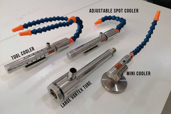
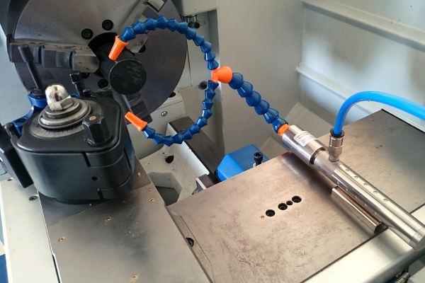
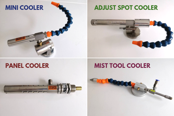
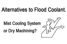
One major “spot cooling” application is the cooling of cutting tools during cutting, drilling, or routing process. Traditionally cutting fluid is used in machining but there is a slow but steady movement to “dry” or “near dry” machining because of the increased safety and especially environmental concerns involved with cutting fluids. Cutting fluids need to be properly disposed of, so there are costs of not only buying the fluid but also the disposal of the fluid. One of the reasons progress is somewhat slow in adapting to dry machining is that cutting fluid not only cools, but also lubricates and cleans the machine tool as it operates. This is where mist cooling systems can come in handy because it is not completely dry allowing lubrication but limits the need for cutting fluid. That being said, dry machining is actually necessary for some materials such as glass, plastic, ceramic and titanium. Vortex Tubes produce the cold air which is blown onto the cutting tool to keep heat down and actually produce a better cut and speed up the machining operation. Often these vortex tubes are packaged with an easy to mount system such as the Nex Flow Tool Cooler.
In some machining application, as when a hole must be drilled deep into a part, some lubrication is required. Nex Flow developed the patented Mist Cooler to provide the necessary lubrication by misting lubricant “cooled” by the vortex tube.
There are of course many other systems developed and being developed to spot cool for machining and eliminate coolant using inert gas for example but the vortex tube is also an integral part in many of developments because they only use “air” and cost in comparison is usually much lower. Cooling gas samples in gas analyzers is another good application for vortex tubes. Industrial camera and all sorts of sensors are used in production more and more, and many of these devices are in very hot areas on a production line. Vortex tubes are compact enough to be used to cool these products and keep them functioning effectively and with no maintenance compared to any other alternative.
Other spot cooling applications addressed by vortex tube technology are numerous and limited only by imagination. Some applications for vortex tubes include cooling the nip roll in a plastic converting process for example to prevent sticking, cooling the head of lasers to prevent heat buildup, setting hot melt adhesives so the glue dries faster and to maximize throughput.
Alternatives in such applications can be much larger in size but vortex tubes are very small. Larger size also typically translates into larger capital cost. As vortex tubes have no moving parts, their maintenance is virtually zero and as long as the compressed air is filtered, their life is as long, or even longer than the equipment they are used with. Compact, zero maintenance and low cost are the key advantages of using vortex tubes for spot cooling over other alternatives.
Utilizing vortex tube technology for cooling enclosures is another major application. There are many ways to cool electronic enclosures and other enclosures with traditional air conditioners. However, factory environments can range from quite benevolent to very harsh. A carbon producing facility will be very dusty. This dust can easily get into control cabinets and cause havoc to the electrical components inside. The limitation on the use of vortex tubes is the amount of compressed air available in any facility. The cost is also a major consideration as compressed air is costly. Where vortex tube based products such as the Nex Flow Panel Cooler become an advantage is when the increased energy cost offsets the cost savings in equipment maintenance costs in both material and time, and in offsetting damage to the controls. It is for very hot, humid or harsh factory environments, that increased energy cost of vortex tube cooling systems can be offset by the savings in maintenance time, materials, disposal of filters and improved control life because they keep out the nasty environment from the cabinet enclosures.
Vortex tube controlled cabinet coolers, like the Nex Flow Panel Cooler, have proper electrical certification to assure that no moisture can enter the cabinet. For example, the Nex Flow Panel Cooler models are available to mount onto cabinets with NEMA 12 (IP 54), NEMA 3R (IP 14) and NEMA 4X (IP 66) classifications.
Vortex tubes for these small “spot” and such “enclosure” applications are both a cost-effective and simple solution where cooling is required.
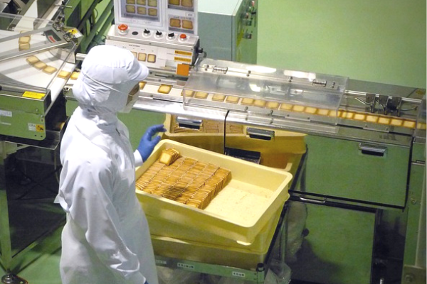
Compressed air is safe, reliable, and used in packaging products. The compressed air systems move materials from one area of the factory to another, perform blow-off, part drying, and align products for packaging. Bakeries use compressed air for blow-off applications, while others use compressed air to clean containers before filling them with products. Compressed air technology is also used to cut, sort, shape, and convey products, such as food, from one location to another in a factory.
Cartons are also formed, filled, and sealed using compressed air. The quality of compressed air can vary widely depending on its application. The food industry requires the highest level of safe, clean compressed air to handle and package goods. Pharmaceutical industries also require more stringent clean air than other industrial applications because they are either ingested or injected.
Clean, high-quality compressed air is required in pharmaceutical and food packaging to ensure consumer safety and prevent product contamination. It is essential to have either no contact with the product or contact using pure air to avoid product recalls, damage to brand reputation, or litigation. Pneumatic systems are recommended because there is no chance of leaking oil as in hydraulic systems.
Pneumatic systems do not pollute or release contaminants into the atmosphere, so they are especially useful for packaging food products. These systems have no moving parts, so there is less maintenance and downtime compared to other systems.
Using Compressed Air in Packaging
Clean compressed air is essential for food and pharmaceutical processing and packaging operations. Compressed air must be purified, especially when the product is consumed. Compressed air conveyors are the best technology to ensure safe food quality. Contaminants include spores, solid particulate, vapors, and moisture. Oil is often not an issue with compressed air conveying systems, unlike hydraulic systems, which use oil as a medium.
To stop microorganisms and fungi growth, the dew points of air at line pressure must be -25 degrees Celsius (-15 degrees Fahrenheit). Standards have been developed that state very fine filtrations to prevent particulate and oil from contaminating food products.
How does Compressed Air Keep Products Dry and Free of Contaminants?
Equipment performance is only as good as the quality of air. Any atmospheric air contains some moisture and dirt. No matter how small the contaminants are initially, they are concentrated when the air is compressed as the air heats, its ability to hold water vapor increases. The vapor condenses into liquid when the air begins to cool as it travels downstream. Maintenance by plant operators can remove liquid, particles, and contaminants. Air dryers are installed to reduce moisture.
They lower the dewpoint of the compressed air to prevent water droplets from forming downstream. There are four types of dryers: Refrigerated, chemical, regenerative, and membrane or mechanical. Mechanical filters work with compressed air dryers to remove contaminants and water. There are three types of filters: Particulate, coalescing, and adsorption.
After the appropriate filter has been added to the conveying system to ensure that the compressed air equipment does not introduce contaminants, equipment that is used to blow off products before packaging is added, examples of this type of equipment include engineered nozzles and air knives. They conserve compressed air by using the Coandă effect to entrain surrounding air along with compressed air to create a high-flow velocity stream of air.
What are some things to remember when using Compressed Air Products for packaging?
If used as intended, compressed air will not generate biological, chemical, or physical hazards while packaging goods. The manufacturer is responsible for producing final products that are sanitized and free of contaminants such as oil, microorganisms, particulate or dust. Manufacturers that use the compressed-air system must carefully consider productivity and production costs against safety.
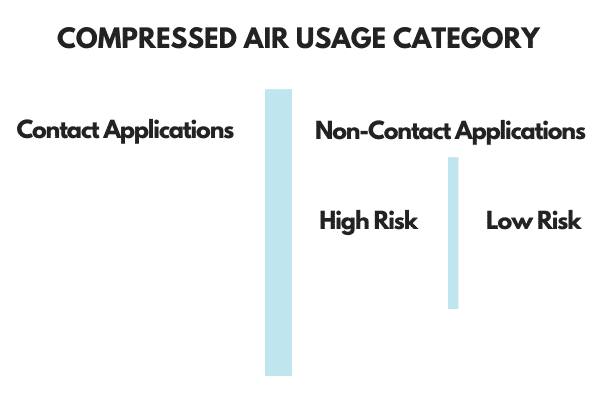
Compressed air used in packaging will often come into contact with the product. “Contact Application” is defined in the British Compressed Air Society (BCAS)/ British Retail Consortium (BRC) code of Practice for Food Grade Air code as “the process where compressed air is used as part of the production and processing including packaging and transportation of safe food production.” This means that packaging and moving products with compressed air is a contact application.
Other examples of compressed air contacting the product include blowing off the water after washing a product and before packaging, cooling a product to increase line speed, and blowing off excess ingredients (such as sugar) before cooking. Non-Contact Application is “the process where compressed air is exhausted into the local atmosphere of the food preparation, production, processing, packaging or storage.” Non-contact applications can be categorized into 2 additional sub-categories (high risk and low risk).
Using Compressed Air in Packaging
When designing a compressed air system for conveying, it is important to use filters and air purifiers to ensure compliance with various safety and manufacturing standards. The BCAS/BRC Code of practice recommends testing the machinery installation twice a year for contaminants such as microorganisms, particles (dirt and dust), humidity, and oil contamination. Refer to this article to learn more about the requirements in the food industry or the standards in the pharmaceutical industry.
With regards to filtration, a centralized air drying and filtration system should suffice if the pipes are relatively new in the facility. However – if the pipes are polluted or hard to clean – it is better to have both a centralized filter as well as a decentralized filter installed upstream of the point of use. New or cleaned pipes are also recommended of zinc-plated steel for food applications, V2A/V4A, compressed air-approved plastic, or aluminum.
How does it work?
The Packaging industry includes a wide variety of materials and products since almost every manufactured product is packaged: toys, food, soft drinks, beverages, cigarettes, cosmetics, brushes, kitchen accessories and more. All the products move down the assembly line before packaging. The packaging process consists of transportation lines made of pipes or ducts to carry a mixture of products and materials along a stream of air.
The pneumatic conveyor system consists of interconnected transition lines, hoses, cylinders, a gas compressor, standard cylinders, and gas (atmosphere). The compressor generates the air flow and transmits the material through a series of hoses. Manual or automatic solenoid valves control the air flow—a centrally located and electrically powered compressor powers cylinders, air motors, and other pneumatic devices. Pneumatic systems are controlled by a simple ON/OFF switch.
There are three conveyor systems that generate high-velocity air streams: a suction system/vacuum system, a pressure system, and a combined system.
A suction or vacuum is used to move light-free-flowing materials. The system operates at 0.5 atm below atmospheric pressure.
A positive pressure compressed air conveying system is used to push material from one point to another. This type of conveyor operates at a pressure of 6 atm or more.
The combined suction/pressure conveying system is used to convey material from several loading points (suction) to deliver to several unloading destinations (push).
What are some Nex Flow products applied to packaging items?
Pneumatic systems are highly recommended when manufacturing, moving or packaging any product that will be digested or inserted in a living organism, such as food or pharmaceutical goods, since there is no chance of contamination due to burst pipes or oil leaks. Nex Flow manufactures compressed air products that help companies to package goods by supplying machines used for industrial cooling (Vortex tubes), part cleaning, drying, and blow-off, and air-operated conveying before packaging.
Nex Flow engineered air optimization design improves safety while increasing manufacturing and packaging productivity and decreasing energy costs. The air-operated conveyor systems sold by Nex Flow can replace traditional conveyor belt systems, which have higher operational costs because they need to be regularly maintained.
Spot Cooling
Nex Flow pneumatic products provide the best spot cooling and blow-off solutions for materials before packaging. Vortex tubes convert compressed air into very cold air for spot cooling for industrial applications. Small vortex tube-operated mini-coolers and vortex cooling can provide extremely cold temperatures for spot cooling before packaging without refrigerants, such as CFCs or HCFCs. Vortex tubes improve factory safety and reduce noise for workers in a manufacturing environment.
Blow-Off Products
Effective, engineered blow-off products manufactured and sold by Nex flow include air knives, air amplifiers, air jets, and air nozzles. These products are another example of how Nex Flow strives to improve the safety of manufacturing and factory environments because they meet OSHA noise and pressure specifications. Among many other applications, air amplifiers are used to clean and dry parts and remove chips and part ejection.
Air knives and nozzles are used to flip open and close the tops of boxes during packaging. Air blade ionizers effectively remove static that could trap the dirt while using plastic wrap for packages.
Conveying Systems
Compressed air-operated conveying systems move materials and products at high speeds over long distances. Ring Vac Operated conveyors, and X-Stream Hand Vac are used for conveying materials where vacuum force is required to move products over long distances at high rates. Ring Vac Air operated conveyors were originally designed to help with bending and lifting goods. The speed of conveyors depends on the density of the materials (lbs./cubic foot), horizontal distance, and vertical lift.
A Ring Vac operated conveyor is a simple, low-cost solution to other pneumatic conveying systems. They are available in several materials depending on the application. Ring Vac operated systems are made of anodized aluminum or stainless steel. 316L Stainless Steel pneumatic conveyors are used when moving food and pharmaceutical products or packaging. It is available in regular and high-temperature stainless steel for high-temperature and corrosive environments.
The X-stream® Supreme Pneumatic Conveying System (XSPC) is an air-operated conveyor that uses compressed air for an efficient and power venturi action along the length of the non-clogging design. The compressed air system is designed to transport or vent lightweight items and raw materials for packaging at high rates over long distances.
The cost-effective systems are ideal for continuous or intermittent use since they are operated by a simple on/off switch and are controlled by a regulator. All Nex Flow conveyor systems are simple, easy to install and use, compact, portable, and maintenance-free.
Other benefits of compressed air-operated conveying systems are also reliable since there are no moving parts and low maintenance costs. These systems have no angles to collect contaminants such as moisture, particulate debris, or microbiological growth. They are safe for any factory environment because the system is powered by compressed air and not electricity.
Mufflers, filters, mounting systems, and static control for blowing off dust and debris from statically charged surfaces are available through Nex Flow to improve factory production and efficiency in assembly and packaging goods.
Trust Nex Flow to provide the most efficient, reliable, maintenance-free compressed air solutions for packaging your goods so that they are clean and safe for your customers.
Using Compressed Air in Packaging FEATURED PRODUCTS
Vortex tubes are ideal for spot cooling and enclosure cooling. Typically one vortex tube is used for one “spot” and for “one” enclosure. But there are some situations where one vortex tube can be split into multiple “spots” as long as one important criteria is kept in mind. Once the compressed air exits the vortex tube it needs to be directed to the area that needs the cooling. When the vortex tube is out in the open, this is achieved by adding a delivery tube, usually flexible tubing to direct the cold air to that spot. When cooling an enclosure, the cold air is sent directly into the enclosure from inside the enclosure. Once the air exits inside the enclosure it can be further distributed around the enclosure thru tubing but all the cold air is input into the enclosure.
Two factors that must be considered when using the cold air produced in a vortex tube: conduction and pressure drop. The general rule it to keep any tubing on an open space vortex tube as short as possible, preferably under 8 inches. One example where a vortex tube has been used in open space for multiple locations is on routing a plastic part. Once Nex Flow Model 50030H vortex tube had the cold air split into two directions and delivered to cool two routers. Rather than using one vortex tube for each router, one larger capacity vortex tube was utilized. If two separate units were used, they could have been smaller capacity units (Model 50015H), each which is ½ the capacity of what was used. What made this work was delivering the air with large (10 mm) tubing to offset pressure drop and keeping the distance as short as possible (under 8 inches to each router). Also, the tubing was insulated to minimize the effect of conducting heat from the surroundings into the tubing, heating up the cold air. There was consideration for using two vortex tubes but there were also space issues with the application.
But this is not a common application. If the distance they had to cool was much longer from the vortex tube, we would have recommended two of the smaller capacity vortex tubes. There is another consideration when considering the use of vortex tubes for multiple location cooling. Let’s take the example above. If the distance from the vortex tube was only a few inches more, to get the same cooling effect at the router, we would have had to use a larger capacity vortex tube, a Model 50040H. That extra 10 SCFM of compressed air use costs energy. That extra energy cost would more than pay for the extra vortex tube in a very short time, and even if used sparingly, certainly in under a year. The increased operating cost, even with minimal use, can easily be equal to or more than the capital cost of one additional unit.
Concerning enclosures, more than once we had to address an issue with cooling when a Nex Flow Panel Cooler, instead of being attached directly to the control panel. Was for some reason mounting off to one side, and a tube was attached to the bottom of the Panel Cooler and then put into the control panel. Needless to say, the unit did not cool as was expected because the cold air heated up several degrees before it reached the control panel. The Panel Cooler has a built in vent to exhaust the displaced hot air inside the cabinet and of course was not used at all when mounted outside. If you are facing any difficulties with installation – please do not hesitate to contact one of our engineers.
Another thing to remember when installing a vortex tube or a vortex tube operated device like the Panel Cooler, onto an enclosure that it must be installed at the top, or if space is lacking, near the top using a side mount. The reason is that cold air falls and hot air rises. The reason a distribution tube is used at the end of a Panel Cooler is to distribute the cold air faster to isothermalize the cabinet (even out the temperature) more quickly. If the vortex tube device is mounted too low, the hot air will tend to stratify at the top of the inside of the enclosure.
When considering any vortex tube operated device – cabinet enclosure cooler, tool cooler, spot cooler, mini cooler or the vortex tube itself, it is best to keep any attachment at the cold end as short as possible when the product is in open space. When attached to an enclosure of any type, the cold air should be directed directly into the enclosure, near or at the top.
One of the major contributors to the destruction of the ozone layer was chlorofluorocarbons or CFC’s used in air conditioning and refrigeration. Work on alternatives for CFC’s in refrigerants began in the late 1970s after the first warnings of damage to stratospheric ozone were published. This led to the creation of Hydrochlorofluorocarbons (HCFCs) which are less stable in the lower atmosphere. This resulted in the redesign of some equipment as well as replacement of materials which were negatively affected by using the new HCFC’s. The main advantage that HCFCs have over CFC’s is that they are much less stable and more reactive with their additional hydrogen atom(s), meaning they can usually break down in the troposphere before reaching the stratosphere and attacking the ozone. The HCFC’s are actually interim replacements for CFC’s because they still deplete stratospheric ozone, but to a much lesser extent. Ultimately, hydrofluorocarbons (HFCs) will replace HCFCs. Unlike CFCs and HCFCs, HFCs have an ozone depletion potential (ODP) of 0. HFCs were developed in the 1990’s as a replacement to the ozone-damaging chlorofluorocarbons (CFCs) and hydrochlorofluorocarbons (HCFCs). They are now the most dominant cooling agent in new refrigeration, air-conditioning (AC) and heat-pump equipment.
While most modern-day refrigerants are hydrofluorocarbons (HFCs) – they have recently been scrutinized as being a potent greenhouse gas. a problem. HFC’s are widely used in air conditioning systems and their usage is anticipated to rise, with their negative impact on global warming also being predicted to increase.
So now there are plans to phase-out HFCs in air-conditioning systems and new replacement fluids are currently being investigated but options are limited.
HFCs replaced HCFCs in many AC systems, but even now HCFCs are still used in developing countries. Even though the replacement of CFCs and HCFCs by HFCs reduced the risk to the ozone layer, they still possess enough high global-warming-potential (GWP) to warrant research efforts into finding an alternative solution. Refrigerants are the essential working fluids in a vapor compression refrigeration cycle. They absorb heat at low temperatures in the evaporator and release it at high temperatures through a condenser.
There are only a few pure liquids and blends that have the potential to be used as refrigerants to replace HFC’s. Most of the fluids that seemed to have potential at first turned out to be classed as flammable or mildly flammable. Six of these slightly flammable, novel molecules were identified, but present unknown risks, are tetrafluorodioxole, trifluoromethanethiol, trifluoropropyne, difluoromethanethiol, (E)-1,2-difluoroethene (R-1132(E)) and tetrafluoromethaneamine. The flammability of course is a problem.
The other potential is refrigerant blends. 1,1,2,2-Tetrafluoroethane (commercially known as R-134) is a molecule that has been previously considered but was never used commercially. It is now being stipulated that it could be a good candidate for refrigerant blends. Refrigerant blends are currently being developed and tested, and although they don’t perform as efficiently as pure fluids, they minimize the flammability and in some cases, can remove the risk completely. It is a compromise that is being considered and developed, but it does not offer the ‘ideal’ refrigerant that many people are searching for. The problems in finding a new pure refrigerant not only lies in flammability. There are also limitations on size, as the thermodynamics only allows for small molecules, of which there are a finite amount. The unknown risks of some molecules promote the apprehensiveness to use such molecules as years of R&D could yield a useable molecule, so a number of people willing to take a chance on these molecules will be low- even if there is potential. Barring the discovery of a fantastic refrigerant blend, or dealing with the flammability issues, if these are the best choices, what chance do we have of efficiently replacing HFCs?
There is however, an alternative that should be considered at least for smaller applications when compressed air is available in industrial applications. That is vortex tube technology. The vortex tube, also known as the Ranque-Hilsch vortex tube, is a mechanical device that takes compressed air and splits the air flow up in such a way that it exits the tube hot at one end and cold at the other. Invented in 1931 by the French physicist Georges J. Ranque, it was commercialized in the 1960’s and still used extensively to day for spot applications (spot cooling) but also to cool electrical and electronic control panels, in particularly very harsh factory environments. One of the issues with vortex tubes is that they operate using compressed air. While great for the environment (they only use the air we breathe!) the high energy cost of compressed air has to be considered. In very dirty factory environments however, this higher energy cost is offset by the higher maintenance costs saved when using traditional air conditioners. In difficult manufacturing environments, standard air conditions have to contend with frequent filter changes, higher levels of breakdown and therefore higher repair costs, shorter life, and more frequent refrigerant replacement due to vibration (which only harms the environment more). Vortex tube technology can actually produce temperatures as low as -40 C or even lower in some cases with virtually zero harm to the environment and require very little maintenance.
Vortex tube technology has not changed much since the 1960’s but is due for efficiency enhancement. If these devices can be improved in efficiency even modestly, they can be used more and more in at least industrial environments. Compressed air is not flammable, does not harm the ozone layer and does not contribute to global warming. If a manufacturing facility is using air conditioners for cooling control panels and even for other cooling applications, they should evaluate their maintenance costs, machine life, the internal labor costs to maintain them, and even the cost of disposing used filters. If the cost is relatively high, they should consider vortex tube technology as an alternative. Vortex tubes have virtually zero maintenance and as long as the compressed air supply is filtered to keep out moisture and dirt, the devices have a lifetime of use with zero maintenance. Apart from cooling control panels and any electrical and electronic cabinets, they find use in all sorts of spot cooling applications because they are so rugged and compact. They are used to cool tooling for example in dry machining. The technology is finding increased usage for machining in the move away from coolant for environmental reasons. CO2 is sometimes used to cool in dry machining but again, you have global warming issues. Cooling molds with vortex tubes is possible by blowing cold air into the mold cavity. Welds are cooled in metal can production using vortex tubes. Cooling cameras or sensors in factories that are exposed to a hot environment is a major application where vortex tubes are used and provide a great benefit where traditional air conditioning devices would not work well. Basically any open “spot” or any hot enclosure can potentially benefit from vortex tube technology.
There tends to be a stigma against the use of compressed air due to the high energy cost but when considered against environmental cost of alternatives, and against the traditional capital costs, and maintenance costs, it becomes more and more attractive as time goes on. Traditional air conditions will become more costly as alternative refrigerants are adopted for the simple reason that their lower stability means change of internal materials and the cost of the refrigerants themselves. Vortex tube technology will only become more attractive, at least for industrial applications. It does not deplete the ozone, does not contribute to global warming, and uses only the air everyone breathes.
In a previous article, we’ve explained why it’s not practical to use vortex tube to cool a room. Another question that gets asked sometimes is – can I cool a small server with a vortex tube and that answer is generally no but it is possible to cool small individual servers. Computer equipment generates heat, and are sensitive to heat, humidity, and dust. If we’re talking about a computer server – there is also a need for very high resiliency and failover requirements. Maintaining a stable temperature and humidity within tight tolerances is therefore critical to IT system reliability. According to OpenXtra, server room temperatures should not dip below 50 ˚F (10 ˚C), and should not exceed 82 ˚F (28 ˚C). The optimal temperature range is between 68-71 ˚F (20-22˚C). So, when you have numerous servers on the premises for your business, heat and power will be some of your primary concerns. A single server can generate quite a bit of heat and when combining several together with other equipment in a closed room, temperatures can quickly add up.
In principle it is easy to calculate the size of air conditioning unit you need for your Server Room, just add together all the sources of heat and install an air conditioning unit that can remove that much. In practice, however it is more complicated.
Fire regulations often require that Server Rooms have levels of insulation far above that of a normal office. Providing sufficient cooling is essential to ensure reliable running of servers, routers, switches and other key equipment. Failure of air conditioning can lead to serious consequences for the equipment itself and for your company. Early warning of problems and spare capacity in the cooling system are both highly desirable.
The amount of heat generated is known as the heat gain or heat load. The heat load depends on a number of factors, by taking into account those that apply in your circumstances and adding them together a reasonably accurate measure of the total heat can be calculated*.
Factors include:
The floor area of the room
The size and position of windows, and whether they have blinds or shades
The number of room occupants (if any)
The heat generated by equipment
The heat generated by lighting
Follow these 5 simple steps to calculate Total Heat Load:
Calculate the amount of cooling required depending on the area of the room. Room Area BTU/hr = Length (m) x Width (m) x 337
If there are windows to your server room – do the following calculation. If there are no windows – then skip steps 2 and 3. *note: This if for the Northern Hemisphere. If you are in the Southern Hemisphere swap the conversion factors as the heat on North facing windows is then greatest. South Window BTU/hr = South window Length (m) x Width (m) x 870 North Window BTU/hr = North window Length (m) x Width (m) x 165 2.1 If there are no blinds on the windows multiply the result(s) by 1.5.
2.2Calculate heat load for all windows combined. Total Windows BTU/hr = South Window(s) BTU/hr + North Window(s) BTU/hr
Purpose built Server Rooms don’t normally have people working in them, but if people do regularly work in your server room – you can calculate the heat output if any personnel in the room (around 400 BTU/hr per person) Total Occupant BTU = Number of occupants x 400
Estimate the Equipment and Lighting heat load. The wattage on equipment is the maximum power consumption rating, but the actual power consumed may be less. However it is probably safer to overestimate the wattage than underestimate it. Equipment BTU/hr = Total wattage for all equipment x 3.5 Lighting BTU/hr = Total wattage for all lighting x 4.25
Calculate Total Heat load by adding the above together. Total Heat Load BTU/hr = Room Area BTU/hr + Windows BTU/hr + Total Occupant BTU/hr + Equipment BTU/hr + Lighting BTU/hr
This is the amount of cooling required so you need one or more air conditioning units to handle that amount of heat. Generally this load will be quite high for using vortex tube operated Panel Coolers.
So what size of air conditioner do you really need?
Small air conditioning units have a cooling capacity of between 5,000 and 10,000 BTU/hr. Small units may fit in windows, venting to the outside environment. Panel Coolers can provide up to 2800 BTU/hr of cooling. Larger air conditioning units may be rated in tons of cooling. 1 ton of cooling is equivalent to 12 thousand BTU/hr.
While vortex tube operated Panel Coolers can cool a small individual server, cooling the entire room can be a problem for several reasons. First, a Panel Cooler or a Cabinet Enclosure Cooler that operates with vortex tube technology, works by providing cold air into the item cooled. But the waste heat is dispelled into the room. If you have multiple Panel Coolers, that can add up to a great deal of heat. The only way to regulate that heat added is to vent that waste heat outside the room from each Panel Cooler. So the server may be kept cool, but not the room. That waste heat needs to be removed. Secondly, because Panel Coolers use compressed air, a large number of units requires a larger compressor which in turn can add to energy costs.
While it can be practical to cool a small server with a Panel Cooler for cooling a dedicated server room it is generally not practical.
Galvanic Corrosion – What it is and how to prevent it?
Galvanic corrosion (also called bimetallic corrosion) is an electrochemical process in which one metal corrodes preferentially when it is in electrical contact with another, in the presence of an electrolyte. This occurs in batteries for example where the cathode stays whole and the anode corrodes as the battery is working. Contrary to some believes – Galvanic corrosion does not only occur in water. Galvanic cells can form in any electrolyte, including moist air or soil, and in chemical environments. As an example, Over 200 years ago, the British naval frigate Alarm lost its copper sheeting due to the rapid corrosion of the iron nails used to fasten copper to the hull. The electrolyte in this case was salt water creating a galvanic cell.
In the case of the Alarm, the iron acted as an anode and was corroded at the expense of the copper which acted as the cathode. Just two years after attaching the copper sheets, the iron nails that were used to hold the copper to the ship’s underside were already severely corroded, causing the copper sheets to fall off.
Metals and metal alloys all possess different electrode potentials. Electrode potentials are a relative measure of a metal’s tendency to become active in a given electrolyte. When in the same environment, the more active a metal is likely it is to form positively charged electrode (anode) and the less active metal is more likely it is to form a cathode (negatively charged electrode).
The electrolyte acts as a conduit for ion migration, moving metal ions from the anode to the cathode. The anode metal, as a result, corrodes more quickly than it otherwise would, while the cathode metal corrodes more slowly and, in some cases, may not corrode at all.
The Nex Flow Difference Allowing Products to Last Longer than Competitors
While products such as air knives, air nozzles, air amplifiers, vortex tubes, etc. are not necessarily immersed in any electrolyte, if the environment is humid, or if the equipment is subject to wash down procedures, it is very possible that this type of corrosion can occur. One example is mixing stainless steel and aluminum. There was one example where a competitive cabinet enclosure cooler was observed with a big hole on its side after some years of use. The stainless steel vortex tube inside combined with the aluminum housing, and the factory environment, over time caused the aluminum to act as an anode and started to corrode.
Nex Flow® takes certain steps and actions to prevent this from happening in their products allowing the products to last longer. The first is to protect aluminum that is used, especially if combining it with steel or stainless steel. Our aluminum air knives for example – are anodized and as such have a protective coating to prevent an “electrical circuit” with the stainless steel shims used inside and the stainless steel screws used to hold the air knife together. In addition, the aluminum would tend to act as an anode anyway in an electrolytic environment and being so large compared to the stainless steel shim corrosion would be minimized. Regardless of whether galvanic corrosion would occur, the anodization also protects the air knife from any environment which bare aluminum is unprotected. Similarly, Nex Flow anodizes all their aluminum parts – air knives, air jets, nozzles, air wipes and air operated conveyors such as the Ring vacs. Air amplifiers and flat jet nozzles which are aluminum zinc-cast are powder coated for longer life and also look better.
When it comes to vortex tube technology, such as cabinet enclosure coolers (panel coolers) and tool coolers, no aluminum is used. It is stainless steel with some brass internal parts. This works to ensure that you will not find any holes in Nex Flow Panel Coolers caused by galvanic corrosion ever. So when shopping for products to blow off, clean, move, and cool, look not only at the performance data, design and workmanship – all which are important of course – but also refer to the quality and type of material used in construction. You can also refer to this article on how to avoid galvanic corrosion. Remember that materials used and how they are put together does make a difference.
Spot coolers are self-contained air conditioning systems that have all the components of larger air conditioning systems but are compact and easy to move. Spot cooling for industrial applications are used short term to cool a small area on a part or in an enclosure – such as a cabinet. Spot coolers are ideal for cooling electronics, computer server rooms, and humans in small confined work environments. They are often praised for their portability, ease of use, and installation.
Fans cannot cool below ambient temperature because they cool by moving air and cool a wider area. Compressed air amplifiers cool better than fans because of the higher velocity but they also do not cool below ambient temperatures. Air amplifiers also cool a wider area. This blog discusses the three most popular ways to cool below ambient temperature, namely Vortex Tubes, thermoelectric, and cryogenic gas (CO2 and Nitrogen Gas) cooling systems.
It is important that the spot cooling system chosen is reliable because sudden or frequent break downs can cause costly equipment damage, repair, or replacement. Keeping humans cool in a small work area is important as well for health and safety concerns. All Spot coolers come with accessories that allow you to direct the cooled air where it is needed most. Any condensation that results from the cooling process is drained through a hose or bucket.
Vortex Tube Cooling System
Vortex Tube Cooling systems are powered by compressed air. The vortex action separates the compressed air into extremely cold and hot streams. The cylindrical form causes the compressed air to rotate at a high speed (reaching 1 million rpm). A small portion of the air exits through a needle valve as hot exhaust. The remaining air is forced through the center of the incoming air stream at a slower speed. The action of the slower moving air dissipates any remaining heat into the faster moving air. The super-cooled air flows through the center of the generator and exits the cold air exhaust. Depending on the temperature and pressure of the incoming compressed air, it is possible to achieve cold end temperatures as low as – 40 and even – 50 degrees F. The hot air (end) can be up to 260° F (127° C). The Vortex cooling system, or cold end of the Vortex Tube, is often used for “spot cooling” of cabinets, such as control panels and industrial cameras.
Vortex Tubes normally come with the “hot end” adjustable to control the flow and temperature out the cold end. The more flow out the hot side, the lower the temperature out the cold side. The cooling effect (BTU/hour) is determined by both flow and temperature drop. Therefore, for cooling applications, the cold end should be between 60% – 80%. If the cold temperature is most important, then the flow out the cold end should be under 50%.
Choosing the best Spot Cooler
Factors in selection:
Vortex Tube cooling systems that use compressed air is considered where conventional enclosure cooling by air conditioners or heat exchangers is not possible. Ideally, Vortex Tube cooling systems are used to cool small to medium size enclosures, nonmetallic enclosures, and areas where the size of cooling devices is restricted.
For optimum cooling results when using a Vortex Tube cooling system, the following items are required when installing:
Clean, dry, oil-free compressed air
80 to 100 PSIG / 70 degrees F or below. Lower pressures and higher temperatures will reduce BTU/H ratings.
A 5-micron water and particulate removal
A 5-micron oil removal filter when oil is present
Thermostats or temperature indicator sticker
Valve (optional)
Muffler go minimize exhaust noise
Advantages:
The Vortex Tube cooling system has many advantages. The small, portable, light weight, and compact system creates extremely cold air without refrigerants, included CFCs or HCFCs. It is exceptionally reliable since there are no moving parts and virtually maintenance free. It uses minimal electricity (only for the compressor). Vortex Tube cooling systems are useful in harsh and high temperature environments. Customers can expect a long life from Vortex Tubes because Nex Flow uses only Stainless-Steel with a brass generator. Compressed air is not the only gas that can be used to produce cold air, Nitrogen and other natural gases that can be compressed can be used as well.
Applications:
Vortex Tube cooling systems can be used to cool:
electronic and electrical control instruments
machine operations/tooling
CCTV cameras
Set hot melt adhesives
soldered parts
gas samples
heat seals
environmental chambers
workers wearing protective gear
data centers
plastic machined parts and molded plastics
Electronic components
It is understood that cold and hot gas (bi-product) is generated when using a Vortex Tube cooling system.
Choosing the best Spot Cooler
Thermoelectric Coolers (Peltier Effect)
Thermoelectric cooling (TEC) became a viable option for spot cooling in the late 1950s with the development of semiconductor materials. The thermoelectric cooler (TEC), often called the Peltier module, is named after Jean Peltierwho discovered heating/cooling effect when passing electric current through the junction of two conductors in the early 1800s. It is a semiconductor-based electronic component that functions as a small heat pump.
Using a low-voltage positive DC voltage to a TEC, electrons pass from one element (p-type) to another (n-type), and the cold-side temperature decreases as the electron current absorbs heat, until equilibrium is reached. The cooling is proportional to the current and the number of thermoelectric couples. This heat is transferred to the hot side of the cooler, where it is dissipated into the heat sink and surrounding environment. The result is a quick and large temperature differential.
Factors in Selection:
To use Thermoelectric spot cooling, a DC voltage required. This type of spot cooling is ideal when refrigerants are not desired, and space is limited. It a cost effective, reliable, efficient way to spot cool. Multiple thermoelectric coolers are connected side by side and then placed between two metal plates. It is ideal for intermittent heating and cooling applications because TEC seamlessly switches between heating and cooling.
Advantages:
Thermoelectric spot cooling has come to dominate certain applications because of the following benefits:
Precise temperature control and stabilization to 0.01 degree C
reliable
noise-free operation
vibration-free operation
scalable
compact
Choosing the best Spot Cooler
Applications:
TEC is used for spot cooling for the following applications:
Telecommunication applications:
980nm and 1480nm Pump Lasers
Digital Transmission Lasers
Planar Lightwave Circuits
Optical Channel Monitors
CATV Transmission Lasers
Avalanche Photodiodes
Wavelength Lockers
Medical samples
Cold storage
Electronic cabinets
Self-powered appliances
Small scale refrigeration
Harsh environmental protection for critical components
Computer microprocessors and robotics
Cabinet cooling
Cryogenic Cooling (Carbon Dioxide or Nitrogen gas)
Cryogenics is the scientific study of materials and their behaviors at temperatures well below conventional refrigeration. The word comes from the Greek cryo “cold” and “genic”, which means “producing”. Cryogenic temperature ranges can be reported using any temperature scale, but Kelvin and Rankine scales are most commonly used because they are absolute scales that have only positive numbers. The U.S. National Institute of Standards and Technology (NIST) considers cryogenics to include temperatures below −180 °C (93.15 K; −292.00 °F), which is a temperature above which common refrigerants (e.g., hydrogen sulfide, freon) are gases and below which “permanent gases” (e.g., air, nitrogen, oxygen, neon, hydrogen, helium) are liquids. At 250 F below zero, many gases are liquid. Below is a list of temperatures where these gases boil.
Fluid
Boiling (Celsius)
Boiling (Fahrenheit)
Oxygen
-183°
-297°
Nitrogen
-196°
-320°
Neon
-246°
-411°
Hydrogen
-253°
-423°
Helium
-270°
-452°
Before the fluid’s temperature rise, all the liquid must boil away and turn into a gas. None of these gases exist naturally as a liquid. Each of the gases are cooled to put them into a liquid state. Latent heat absorption during the phase change from solid to liquid or liquid to gas causes cooling in the immediate area. According to the American Society of Heating, Refrigerating and Air Conditioning Engineers (ASHRAE), liquid CO2 (LCO2), known as Refrigerant R-744, is the most widely used method used during vaporization of a liquid to a gas. When liquid CO2 is introduced to the system through the nozzle of a spray gun or cooling injector tube on a temperature chamber or thermal platform (cold plate), the liquid quickly turns to solid state CO2 or dry ice. As the dry ice warms up or sublimates (direct change from solid to gas), a great release of the latent heat occurs.
Liquid CO2:
Spot-cooling method uses liquid CO2 injected in controlled pulses through tiny capillary tubes inserted into hard-to-cool areas to the same level as the rest of plastic mold cores. This approach is meant to complement conventional water cooling by ensuring uniform mold temperature without hot spots.
When the cooling cycle begins, LCO2 is fed under high pressure (approximately 850 psi (58.6 bar)) through the thin, flexible stainless-steel capillary tubes with solenoid valves to time injections and to the points where cooling is required. The high sublimation energy of the CO2 from solid to gas phase, along with the resulting cold gas, provides a very high local cooling capacity. The CO2 withdraws heat from the steel of the mold and escapes out of the expansion room in gaseous form through an annular gap between the hole and capillary tube.
Liquid Nitrogen:
Under normal atmospheric pressure, Nitrogen can exist as a liquid between the temperatures of 63 K and 77.2 K (-346°F and -320.44°F). Below 63 K, nitrogen freezes and becomes a solid. Above 77.2 K, nitrogen boils and becomes a gas. Since it is obtained from the atmosphere, liquid nitrogen is inexpensive and is rarely refrigerated. It is kept in insulated containers called Dewars and can boil away.
Advantages:
Given the purity of LCO2 supplied for this application (typically >99.98%), there is little danger of residue build-up or contamination of the hole as there would be with water cooling. Meanwhile, Liquid Nitrogen is colorless, odorless, and tasteless. It is an Inert element that is noncorrosive and does not support combustion, so it is safe.
Disadvantages:
There are several risks involved in cooling using cryogenic cooling systems. There is always a risk of asphyxiation, frostbite, or burns if not used and handled properly. Cryogenic gas has large expansion ratio for evaporation. For example, if one liter of liquid nitrogen can result in 700 liters of gas. If released in a small room, it can fill a room and make it an oxygen deficient atmosphere. It is also not safe to digest. It is essential that all the liquid nitrogen is evaporated before ingested otherwise it can boil and cause damage to internal organs.
Choosing the best Spot Cooler
Factors in Selection:
Cryogenic spot cooling systems are ideal for specific applications in automotive, medical, aerospace, consumer products, plumbing, and construction. CO2 is the preferred coolant for spot cooling because it is cheap to capture and compress. It is also ideal for large scale applications due to lower volume cost and longer storage times. The cooling requirements should be above -50 C. For repeated cooling, CO2 must be supplied at the right pressure and at the right temperature without gas bubbles. It stores longer than liquid nitrogen gas, which is stored at -190 C.
Liquid Nitrogen cryogenics is colder and has greater heat removing capabilities below -60˚C. Proper supply and control system design is crucial because if too much coolant sublimates to a solid state at once, blockages in the cooling system can occur.
It is highly recommended that oxygen monitoring equipment is used to test for oxygen deficient atmospheres during cryogenic spot cooling. The system must be properly maintained to prevent blockages.
Applications:
Applications of cryogenic spot cooling include:
Cooling of construction mold
Preserve experimental samples
Coolant for computers
Medicine to removed unwanted skin, warts, and pre-cancerous cells
Instantly freeze food and cocktails – creating an impressive cloud of vapor or fog when exposed to air.
Internet searches will find recipes for nitro-caramel popcorn and pumpkin-pie ice-cream
Plastic and rubber deflashing and grinding
Metal treating
Biological sample preservation
Pulverization
Summary
Vortex Tube cooling system is a low-cost choice for industrial applications. Simply adjust the hot end hot air valve to determine the temperature at the cold end. The more air escaping from the hot end reduces the temperature of the cold air flowing from the other end of the Vortex Tube.
It produces cold air instantly for enclosed environments. Since there are no moving parts, there is no spark or explosion hazard. Vortex Tube cooling system have two types of generators that are easily interchangeable. One generator has a cooling effect while the other one restricts the flow of the cold air, which creates extreme cold temperatures such as -40 or -50 F. Apart from special designs, the technology is available in the following configurations:
Packaged Frigid-X® Panel Cooler for cooling control panels
When you need require extreme cold temperatures, Nex Flow recommends using the Frigid-X® 50000C series. Nex flow vortex tub cooling system consists of a stainless-steel body with all metal parts. The cooling system is quiet and instantly creates sub-zero cold air temperatures from an ordinary compressed air supply for spot air cooling applications where precise adjustability of temperatures is important.
Like the Vortex Tube cooling system, Thermoelectric spot cooling is an ideal choice for intermittent cooling/heating applications. The disadvantage is that TEC requires a DC voltage because multiple thermoelectric coolers are connected side by side and then placed between two metal plates. Although equally effective for cooling to extreme temperatures as Vortex Tube or thermoelectric cooling systems for many industrial applications, cryogenic cooling appears to have the highest risks and the greatest need for monitoring equipment for health and safety concerns. Nex Flow specializes in research and development of cooling technology required for industrial fic applications, such as spot cooling. Nex Flow® stays ahead of the competition by finding new applications for this unique technology, and to improve the efficiency of the products which depends on many proprietary factors. Corrosion-resistant, food-grade stainless steel means that all Nex Flow equipment is dependable, and long lasting. All spot cooling equipment is precision machined, assembled, and tested. Manufactured to withstand extreme temperatures and environmental conditions, the Vortex Tube cooling system is produced under strict quality control, which ensures years of reliable maintenance free operation.
Vortex tubes are devices that take compressed air and spins it inside the unit creating a spinning air flow in one direction and spins the air flow back in the opposite direction within the first spinning air flow. Part of the air flow is out one end and gets hot, and the internal spinning flow that is let out the opposite end gets cold. It basically acts like tube in tube heat exchanger.
Air input the vortex tube is normally 80 to 100 PSIG (5.5 to 6.2 bar). The air exiting at each end of the vortex tube goes back to atmospheric or at least to a much lower pressure. In considering what you can or cannot attach to vortex tube, you must first consider these realities:
You need a pressure difference between the inlet air to the unit, and the exit points. If there is no significant difference then the system will not work.
The percentage of the air out the cold end is called the cold fraction. For example, if 80% of the inlet air exits the cold side the cold fraction is 80% and the hot fraction (air out the hot side) is 100-80 = 20%. If you add anything to the cold end, there will be a back pressure. This will affect the cold fraction by pushing more air out the hot side thereby reducing the cold fraction. So there is a practical limit of how much back pressure can be tolerated by attaching anything to the cold end. The ultimate limit is a back pressure that pushes all, or almost all the air out the hot end negating any effectiveness for cooling.
Similarly if you attach something to the hot end there will be back pressure pushing more air out the cold end. The limit would be if all the air is pushed out the cold end – it negates most or all of the cooling effect.
Because compressed air exit at both ends, and at a pressure close to atmospheric pressure, a vortex tube is intrinsically safe from over pressurizing, the ultimate supply pressure limited to material integrity (in the case of Nex FlowTM made products, to 250 PSIG).
So when attaching any other accessory to the vortex tube the concepts above need to be considered. Rarely is any attachment made to the hot air exhaust end except for muffling accessories with minimal back pressure. Even in pre-packaged vortex tubes such as Tool Coolers or Panel Coolers, back pressure is very minimal and typically balanced at the cold end with other attachments such as hose hits or air distribution hose with similar back pressure effects, essentially balancing the system. However, if you examine more closely the cold end attachments, which tend to vary the most, there is a limit there as well. When attaching a hose kit such as locline or similar type of hose, the longer the length the more the back pressure. Locline hose is used extensively with Tool Coolers. The general rule is to limit the locline to 12” and under and to make sure the opening nozzle has at least a 1/8” opening. This keeps the back pressure low. Also, the longer you make this attachment, the air will tend to warm up more because of the conduction of atmospheric temperature through the plastic hose to the inside. So practically, the longer the hose, the higher the temperature (less cold air) exiting. In the case of a control Panel Cooler, there is a hose distribution kit supplied which is basically a long PVC hose with a muffler to attach to the end. Instructions stipulate to create inside this long hose to have at minimum of four (4) holes of 1/8” diameter drilled into the hose to let the air out and blow the cold air from the vortex tube onto the hot parts inside the cabinet. This accelerates the cooling of the inside of a control panel. Again, the minimum number of holes is required to minimize the back pressure (and also to help iso-thermalize the control panel faster). If the holes are not drilled, the cold air will exit only at the exit of hose end and with the added back pressure will restrict the flow, hence negatively affect the overall cooling rate (slows the process of equalizing the cabinet temperature). The hose addition onto a Panel Cooler also acts as a backup in case of a very remote possibility of any moisture getting into the panel in the very rare case that the filter on the inlet air fails. There are instances where a vortex tube has a hose attached to the cold end to deliver cold air at a long distance for other applications. It is important to simply use a larger inside diameter hose, the longer the length to minimize back pressure and if possible insulate the hose from conducting heat into the hose, warming up the cold air travelling inside. Care should be taken that the cold end hose is not fully plugged because while the back pressure will force air back out the hot side, any weakness in the hose may also cause it to split and may be dangerous as a result.
The question frequently arise is if it is possible to attach a vortex tube cold air output to the inlet to a blow-off accessory like air knife or an air amplifier (or any other air amplifying or conveying device). The answer is – it cannot be done simply because of the back pressure requirement of the vortex tube (#3 above). Any air amplifying device requires the air inlet to have high pressure. For a vortex tube to work, the air exit pressure from the vortex tube must be low. So attaching a vortex tube to the air amplifying product will just not work.
But…. the possibility of an alternative approach does come up. There have been a few attempted applications, where the air exiting the cold end of a vortex tube is placed near the air entraining end of an air amplifier such as an air jet or small air amplifier like an FX10, or FX20 or even an FX40. Successful results are rare however, and not confirmed, due to how air amplification technology works. The air drawn in by an air amplifier is depends on the amplifier size. For example, an FX10 will amplify air flow about 6.5 times and consumes 4.9 SCFM at 80 PSG. That means it will draw in a volume of 27 SCFM. (6.5-1 = 5.5 multiplied by 4.9). So if you place a vortex tube cold end “close” to the air entraining end the amplified air can be cooled. Even then, much of that cold air will already be mixed with warmer atmospheric air reducing the cold temperature. And, at the outlet of the amplifier about another 3 times the air is entrained from the warmer atmosphere. Assuming basic adiabatic mixing the cooling effect of the vortex tube supplied air will be greatly reduced. With a larger amplifier, the overwhelming effect of the high volume of entraining atmospheric air overwhelms cooling effect of the small volume of cold air from the vortex tube. This is why mixing the two technologies rarely works.
Air amplifiers and even air knives themselves do cool however, and are used extensively (especially air amplifiers) to cool very hot materials such as castings using the wind chill effect. It’s like driving with the window down in your car while driving on a hot day. The high velocity of the amplified air will accelerate the cooling of the hot surface because the high flow and high velocity of the amplified air cuts through the heat boundary layer on the part to remove the heat fast. One example was from an application in Mexico where small, hot aluminum parts which normally cooled in 30 minutes from sitting on a table were cooled in under a minute using a flow amplifier alone.
Vortex tubes are designed to cool enclosures or for spot cooling and not for cooling large areas. In those applications you are best off using air amplifiers. Therefore, combining vortex tubes with air amplifiers however is not a proven method. When using vortex tubes – it is important to understand the above 4 facts governing the operation of the technology.
The Vortex tube is a mechanical device that separates compressed gas into two extreme temperature air currents. It was initially named the Ranque-Hilsch Vortex tube, after the names of the two initial inventors. It is also known by other names including: Ranque tube, Hilsch tube, or Ranque-Hilsch tube. The description of this device was originally described in the US. Patent No. 1952281 by Ranque Georges Joseph. A second US. Patent No. 3173273A was filed by Charles D. Fulton.
According to Charles Fulton US patent – it is defined as an “apparatus for cooling a fluid flowing continuously therethrough comprising a housing body having an opening for admitting a gas, a vortex generator supported in said body and receiving said gas, said generator having a plurality of nozzles and a circular vortex cavity into which said nozzles discharge said gas tangentially, a seal at one end of said vortex cavity, a discharge line communicating with the other end of said vortex cavity, and a smaller line for receiving said fluid to be cooled passing coaxially through said discharge line, vortex cavity and seal.”
Using fluid dynamic principles and compressed air, the Vortex tube generates gas at very cold and very hot temperatures simultaneously. Compressed air is fed into a compact T-shaped tube with pipes attached to each side. With a simple internal generator, the gas emerging from the “hot” end can reach temperatures of 200 °C (392 °F), and the gas emerging from the “cold end” can reach −50 °C (−58 °F). The owners of this device enjoy an extremely long life with very few issues since the compact device has no moving parts. With the simplistic design and parts, the cost to manufacture and maintain the unit is low. There is also no danger of electrocution or fire. The volume of desired gas flow determines the size of the pipe manufactured. It can be used on any type of gas with consistent results. It is the best, simplest, and most direct method to produce hot and cold air.
The exceptional benefit of the Vortex tube is how little gas pressure is required to produce a large temperature difference in the gas streams.
The requirements for the Vortex tube are:
Compressed Dry gas (otherwise condensation and freezing of moisture needs to be considered)
Insulated tube
How Does it Work?
Pressurized gas is injected loosely into a swirl chamber andaccelerated to a high rate of rotation. With the tapered shaped nozzle, only the outer shell of the compressed gas can escape at that end. The remainder of the gas is forced to return in an inner vortex of reduced diameter within the outer vortex.
The Vortex tube was first explained by observing the geometrical shape and design of the tube and air flow (turbulence, acoustic phenomena, pressure fields). The Vortex tube effect of the compressed gas motion results from the law of energy conservation. The main physical phenomenon of the Vortex tube is the temperature separation between the cold vortex core and the warm vortex margin. It is best described in several steps:
The incoming gas is cooled with adiabatic expansion turning any heat into rotational kinetic energy. The total enthalpy is conserved.
Example of adiabatic expansion is when air rises to the atmosphere and expand due to decreased atmospheric pressure allowing the parcel of air to cool.
The peripheral rotating gas moves toward the hot end. Here the heat recuperation effect transfers the heat from the cold slower moving axial flow to the fast moving hot peripheral flow.
The kinetic energy from the rotating air turns into heat by means of viscous dissipation. As total enthalpy increases from the heat recuperation process – the temperature is raised compared to the inlet gas.
ome hot gas is exhausted carrying with it excess heat.
The rest of the gas is funneled toward the cold outlet where more heat is transferred to the peripheric flow. Although the temperature at the axis and at the periphery is about the same everywhere, the rotation is slower at the axis, so the total enthalpy is lower as well.
This lower total enthalpy gas is “cold” and leaves the cold outlet.
The vortex cooling is due to angular propulsion. As the gas moving towards the center gets colder, the marginal gas in the passage is “getting faster”. The more the gas cools by reaching the center, the more rotational energy it delivered to the vortex and thus the vortex rotates even faster.
Compressed gas at room temperature expands to gain speed through a nozzle. It climbs the centrifugal barrier of rotation during which energy is also lost. That energy is delivered to the vortex, which speeds up the rotating air even more. In a Vortex tube, the cylindrical surrounding wall confines the flow at margins and thus forces conversion of kinetic into internal energy, which produces hot air at the hot exit.
The limiting factor for producing the extreme temperatures is high gas pressure to create the extreme temperature changes in the tube.
Who Invented and Improved the Vortex tube?
Georges-Joseph Ranque (7 February 1898 – 15 January 1973) was the inventor of the Ranque-Hilsch Vortex tube. He was born in France in 1898. At a young age, Georges became interested in physics. In Paris, he studied physics at the Ecole Polytechnique. Afterwards, he pursued a postgraduate degree at the Conservatoire des arts-et-métiers. His initial interest in the operation of the Pantone carburetor led him to study vortices. One of the applications he used the vortex effect was a vacuum pump. His intention was to use his invention to remove dust from a steel plant. While studying the flow of air through a pump, he inserted a cone at one end of the tube, where air was flowing in a vortex and discovered that the stream of air could be split: one hot and the other cold. In 1931, he filed the US. Patent No. 1952281.
Ranque described his tube as having a counter flow and a uniflow type. Through his research he determined that the counter flow tube was more efficient. The counter flow Vortex tube consisted of:
A long slender tube with a diaphragm closing at one end of the tube and a small hole in the center of the diaphragm.
One or more tangential nozzles piercing the tube inside the diaphragm
A throttle valve at the far end of the slender tube.
On the other hand, the uni-flow Vortex tube is similar in structure to the counter-flow Vortex tube, the significant difference is that the uni-flow tube has two exit holes in the same end. This tube appears to have lower efficiency than the counter-flow tube because of the mix of cold and hot temperature flows at the same exit. Since Ranque’s discovery, the Vortex tube has been the subject of much research and study by the scientific community. The primary focus of research was to determine the factors that caused the thermal separation and to improve the performance of the tube.
Ranque saw the commercial potential of the tube he called “Vortex tube“, which means “tube tourbillion” in French. Unfortunately, compressed air systems were not reliable at the time of this invention. The initial Vortex tube was a commercial failure and Ranque’s firm closed a few years afterwards. He continued to work on other fields of research and the initial discovery of the Vortex tube slowly faded.
The Vortex tube would have remained forgotten if it was not for Rudolf Hilsch, a German physicist, professor, and manager of the Physics Institute of George August University of Göttingen, who is credited with improving the understanding and performance capabilities of the Vortex tube. The important research reported in his 1947 paper, Die Expansion von Gasen im Zentrifugalfeld als Kälteprozeß, emphasized that considerable cooling can be achieved by using the Vortex tube in various applications including refrigeration and cryogenics. He cited Ranque’s work in the paper but because of a printing error in the footnote, it was difficult for other scientific researchers to locate the previous research. Therefore, the Vortex tube was briefly known as the Hilsch tube. Now, the importance of this paper allowed Hilsch’s name to be included in the name of the tube so that it is now known as the Ranque-Hilsch tube.
In May, 1947 William Taylor of the National Bureau of Standards published Vortex tube experimental results that described another hypothesis of how the tube works. When compressed air passes through the entry nozzle, it speeds up and loses heat. The velocity gained results in a loss of heat energy. This fast, cold air is then slowed as it spirals in the tube. The molecules of gas drop to the center of the tube. Surprisingly, instead of heating up as they lose speed, they pass their energy to the next outer layer and remain cool. The additional cooling effect is caused by the centrifugal force of the whirlpool. The centrifugal force “throws air molecules” out from the center so that there are fewer molecules and lower pressure. When the air molecules move from the high-pressure region of the tube to the lower pressure region in the center of the tube, the gas expands and cools.
In 1961, a General Electric engineer, named Charles Darby Fulton studied the Vortex tube carefully and developed it for commercial applications. Between 1952 and 1962 he obtained the following U.S. Patents related to the development of the Vortex tube:
US2603535A: Liquid spray nozzle Filed July 15, 1952 INVENTER David C. Ipsen, Charles D. Fulton.
US3208229A: VORTEX TUBE Filed Jan. 28, 1965 2 Sheets-Sheet 2 INVENTOR. CHARLES DA FULTON
provide improvements in the Vortex tube so that they emit colder gas and a larger fraction of cold gas with increased efficiency for a greater range of applications
Reduce leaks
Increased ability to utilize high gas pressures efficiently
Reduce the cost of manufacturing
His company, Fulton Cryogenics, manufactured Vortex tubes and became the Vortec Corporation in 1968 to expand and improve the Vortex product line for industrial and commercial applications. The Vortex tube was used to separate gas mixtures, oxygen and nitrogen, carbon dioxide and helium. In 1991, the Illinois Tool Works acquired Vortec Corporation to further study the Vortex tube for technological applications.
Research for nozzles lead to improvements in the Vortex tube design. Merkulov recommended the tip area being 9% of the cross-section of the tube “with the axial width to be twice the radial depth.” He also inserted a cross in the tube and ultimately shortened the length of the Vortex tube and he received a US patent in 1968 (patent number US3522710A – F25B9/04).
The optimum length of the hot end suggested by Merkulov was 8 to 10 Dc (tube diameter). In 1961, Dr. Parulekar published a paper based on a short Vortex tube:
A cylindrical or convergent piece of axial length equal to 6 mm.
A divergent truncated cone with axial length equal to 18mm.
Cover, which also forms the third part of the hot side is cylindrical and of axial Length equal to 20mm.
In 2001, Guillaume and Jolly performed a study on a two stage Vortex tube where the cold air from the first tube was injected into a second Vortex tube. They reported that the temperature difference at each stage was greater than would be generated from a single stage Vortex tube.
To optimize the performance of the Vortex tube, multi-stage Vortex tubes have been studied. Dincer in 2011 tried a “three-fold type and six cascade type Vortex tube systems” consisting of three and six Vortex tubes connected in a series. Through this research, the greatest temperature drop occurred when six-cascade Vortex tubes were connected.
The curved Vortex tube, studied by Valipour and Niazi in 2011, proved that an increased in temperature difference was influenced by the curvature of the tube. The maximum refrigeration capacity occurred at 110-degree curvature. The maximum temperature difference was generated by a straight Vortex tube.
Other types of Vortex tubes that have been studied include Vortex tubes in various surroundings, insulated, non-insulted and the types of fluids used – such as water instead of compressed air, oxygen, methane and other gas mixture.
Experimentation Discoveries
Ranque discovered through extensive experiments that when the compressed air enters through the tangential nozzle and expanded cold air discharges through a small hole in the diaphragm. Simultaneously, hot expanded gas is discharged through the valve. The coldest gas is produced only when a small fraction of the gas is released through the small hole. It is recommended that the valve is opened widely for this to occur. The result is the hot gas cools to become warm gas. The hottest gas is achieved by closing the valve. Then, nearly all the gas is released through the small hole and is cool.
The two major inefficiencies of this design are:
Only a small fraction of the gas can be extracted at the lowest temperature
The amount of temperature depression obtained never approaches that of an ideal expansion engine.
Continued research is required to determine the optimum configuration is complicated and challenging. There could be up to fifteen factors that need to be considered when optimizing the design. Here are a few:
kind of gas
gas pressure
temperature
rate of flow
cold fraction to be delivered at a certain lower pressure
The research on Vortex tube also involves the compressible fluid dynamics of turbulent and unsteady flow, thermodynamics, and heat transfer. Westley stated, “Besides its possible importance as a practical device, the Vortex tube presented a new and intriguing phenomenon in fluid dynamics”.
Each of the above factors results in a change in condition for the remaining factors. Research to determine the optimized factors of using a Vortex tube continues because of the fluid and dependent nature of research results.
Applications of the Vortex tube
The Vortex tube invention impacted refrigeration, air conditioning, cryogenics, instrumentation, and controls. The Vortex tube excels in situations such as cooling a worker wearing a protective suite or electronic equipment in extraordinary hot environment. Research is often placed on cold gas because of its greatest importance and number of uses. Vortex tubes are useful where sometime heat and sometimes cooling of persons or work environments are required. When using a Vortex tube, it is understood that when cold gas is generated, hot gas is also a bi-product.
Nex Flow strives for excellence and improvements in the Vortex tube technology and original design to best suite an application. Nex Flow provides three standard sizes of the Frigid-X® Vortex tubes:
Mini size – uses 2, 4 or 8 SCFM
Medium size — uses 10, 15, 25, 30 and 40 SCFM
Large sizes — uses 50, 75, 100 and 150 SCFM.
Depending on the temperature and pressure the compressed air used, it is possible to achieve cold end temperatures as low as – 40 (-40 C) and even – 50 degrees F (-45.56 C). Vortex tubes are used to cool electronics, machine operations, tools, CCTV cameras, soldered parts, gas samples, and heat seals. Contact Nex Flow expert technicians to help you decide the best Frigid-X® Vortex tubes for your application.
5 Ways a Tool Cooler is used to Improve Factory Efficiency
A tool cooler is a packaged vortex tube to make it more easily used. A vortex tube creates very cold, and even freezing temperatures from compressed air for spot cooling. By itself, the vortex tube is quite noisy so accessories to muffle the sound of the device is usually required. The tool cooler consists of a vortex tube with a cold end muffler, and a hot end sleeve (to protect from the heat generated at the hot end) which also incorporates some muffling. In addition, a strong magnet is added onto the unit to easily attach it to any magnet accepting surfaces like a machine or steel table to secure the unit in place. So this “packaged” vortex tube is now quiet, easy to handle and more flexible to use.
Normally a vortex tube by itself has an adjustable hot end plug to control the flow of cold air out the cold and hot ends, and to vary the temperature produced at the cold end. But there is an “optimum setting” that will give you the maximum cooling effect and at the same time keep the temperature just above zero degrees C. This is to prevent any possible freezing in the device should the dew point for your compressed air supply is not very low. For sub-zero temperature generation you should have dry air with a dew point below that of the temperature you wish to produce in the vortex tube.
The most common use for a Tool Cooler is of course for cooling the tool used for drilling, grinding, milling and routing especially for materials that are not allowed to have liquid for cooling for various reasons like the liquid being detrimental to the material or for reason such as avoiding contamination. This would be for plastics, glass, ceramics, titanium and other special materials.In fact there is an entire movement to replace coolant normally used as much as possible due to the high disposal cost of coolant and for environmental considerations. Much has and is being driven towards dry or semi-dry machining which involves significant machine design changes as well since liquid coolant not only cools, but cleans away the chips and waste produced in the machining operation.
Tool coolers or variations such as our mist cooler, which offers some lubrication are becoming more popular. But for materials that have always been dry machined such as plastics, the benefits are faster machining (shortens production time and increases output) and better quality, especially with plastics as it produces less waste in the cut (a much cleaner cut). Tool life can be extended as well in carbide tipped tools because the cold air produced helps prevent micro-carbon cracking.
Setting Hot Melt Adhesives is another common use for the tool cooler. When applying adhesives, the cold temperature helps to set the glue faster and allowing for a faster throughput. In one application (which I cannot detail due to secrecy), has a continuous line of adhesive applied and required rapid cooling which several tool coolers along the length of the process was able to provide. The customer utilized adjustable vortex tubes prior but the problem was actually personnel continually adjusting. As such, some devices were adjusted for higher flow, some for colder temperature but – what slipped the mind is – consideration for the cooling effect change. Our tool cooler is set for optimum cooling and took this issue out of the equation. Nex Flow do also offer adjustable spot coolers in cases where some temperature control is needed.
In line slitting, is a variation in tool cooling in that you are applying the cold air flow to a cutting blade in a slitting operation. The advantage here is not for increasing output, but to have the sharpness of the blade last longer. There is a very noticeable improvement when thicker material need to be slit as the blade would have to work harder and can heat up more. The vortex tube operated tool cooler keeps the temperature down, and extends the blade life. As with the adhesive application, the tool cooler is preset to give the optimum cooling effect to prevent tampering with the unit and maintaining consistency in cooling to control the quality of the adhesive application.
Laser cutting is an application where the tool cooler is very effective. For the laser processing of materials, the material changes in the heat affected zone (HAZ) is an important indicator for quality in microelectronics manufacturing. In laser cutting you focus beams to heat the surface of the material up to a high temperature to melt the material and you want to minimize the HAZ. The cooling from the tool cooler decreases potential burning in the heat affected zone area thereby improving quality. As there is no refrigerant involved, there is no effect on the environment. The low temperature cooling air diminishes the HAZ in laser cutting for glass fiber reinforced composite materials for example.
Chill roll nip cooling is where the Tool Cooler is placed on the nip roll of a plastic film web processing line. Nip rollsor pinch rolls are powered rolls that are used to press two or more sheets together to form a laminated product. The high pressure created at the nip point brings the sheets into intimate contact, and can squeeze out any bubbles or blisters that might cause a defective bond. If the material is too warm it can stick and if the material is very thick or cooling is uneven, there could be a hot spot causing defects which is easily eliminated by using a Tool Cooler.
In all these applications there is no requirement for lubrication. However, there are applications where some lubrication is absolutely necessary. One example is drilling a deep hole into a material. Without some lubrication to the cutting tool, it will bind inside the material being drilled. For this reason Nex Flow developed the patented Mist Cooler which operates not by cooling the tool directly, but by cooling the lubricant applied to the cutting tool to a very low temperature. The liquid is applied as a mist to the cutting tool to provide both the lubrication and cooling it needs. The benefit is the diminished volume of liquid needed to both cool and lubricate. Reduction in chemical use can be as much as 20%, a significant savings even over a short time frame.
Tool Coolers are available in various capacities for cooling depending on the nature of the material being cooled, the rate of throughput and the thickness of the material. There is even a small capacity unit called a Mini Cooler which is used in cutting thin material, and even in sewing operations involving heavy textiles such as jeans and burlap bags where the sowing needles heat up and deform or break thread. The mini cooler keeps them cool. While it is generally a good idea to avoid any adjustable system (as the fixed systems are preset for optimum cooling), the Adjustable Spot Cooler is another packaged vortex tube, very similar to the Tool Cooler but with an easy hand adjustable knob to vary the temperature at the outlet that is available. This is usually used in laboratory applications and for testing where temperature variation is required. Tool Coolers (and other variations) can be specially made to provide sub-zero temperatures if required. The versatility of the Tool Coolers makes it an excellent packaged option for all types of spot cooling applications.
Some product manufacturers require you to register your personal data to obtain drawings and technical data. Nex Flow does not – as we believe “information that will help you in choosing your product should be free and accessible”. Nex Flow has faith in its products, quality and performance and strive to be there for you when needed. Hence, we do not interfere with the privacy of our product users just because a drawing is needed. We truly believe that our transparency, service, openness and good value can help to optimize any plant in terms of efficiency, energy use, sound levels and much more.
If you would like to receive a monthly update from us – you can opt in to our mailing list in which you can cancel at any time. We consider all customers to be partners treated with respect and that – means reasonable access to information that is required for you to work easily and privately.
One of the most useful information required by anyone utilizing Nex Flow products is the products’ performance but they also need to know if the products will “fit” into an application location. Machine builders and designers require drawings of product to be able to easily incorporate them into their designs. This is the very reason why we openly provide our drawings and dimensions to designers and users so you can best choose the product that “fits” your application.
Four drawing formats provided are:
PDF
2 dimensional PDF of a CAD drawing fort customers that just require to get an idea of dimensions
3D PDF
Three dimensional drawing of the products that gives an idea of its real life look
CAD
2 dimensional drawing of the products useable in design
IGS
A data format that makes it possible for Computer-aided design (CAD) systems to exchange information and easily incorporate the product into a customer design
The most common products where these drawings are utilized are:
Nozzle image with
small caption linking
to nozzle page
Air knives
Air amplifiers
Air wipes
Air operated Conveyors
Vortex Tubes
Panel Coolers
The reason being that these products are typically part of a production line that have to be placed and oriented a certain way to work properly and to be assured that they fit for the application.
Other Nex Flow products also have these drawings available even if they are not necessarily incorporated into an initial product design. For example, Tool Coolers, Adjustable Spot Coolers and Mini Coolers come with magnet attachment so they can be mounted easily onto a machine. Sometimes these products are used intermittently because they are not always needed for a particular application or they are moved around and shared between several machines but the information is still necessary to visualize how they can be mounted.
All Nex Flow products need to be connected to a compressed air supply lines, filters, regulators and other types of in line equipment, most often supplied separately by others (although also available by Nex Flow). Machine builders and designers typically go direct to manufacturers of individual products because that is the way to get the best price as well as the technical data and drawings needed. End users usually have standard or existing suppliers for many of the accessories as well.
Air gun drawings are useful to give an idea of how the guns can fit into a person’s hand. There are many low cost – frankly cheap – air guns on the market but many times they are not very well designed for comfort. If the air guns are used extensively, a drawing will help visualize its use in your operation. Of special importance would be heavy duty air guns used for difficult air blow off applications. They need to be especially ergonometric to maximize comfort for the user.
The dimensions of items used in places where space can be a premium is also especially useful – such as vortex tube operated Panel Coolers which are mounted onto control panels but also used for cooling items such as cameras, and vortex tubes themselves. Panel Coolers are normally mounted on the top of control panels and there has to be enough space on the top of the panel, otherwise a side-mount should be used.
Static control technology is another item where drawings are useful in placement of product. Static eliminators and their distance to the product is critical for their effectiveness and they also require a power supply near proximity to the static bar.
Having easy and anonymous access to these drawings makes the job of designing and choosing a product easier, more efficient and also helps to protect the work of the people using the information freely offered by Nex Flow.
Should I use a Mist Cooling System or go the route of Dry Machining to replace Flood Coolant?
Machine operations still commonly use flood coolant but are working on ways to replace with alternate systems. One such system called Minimum Quantity Lubrication (MQL) attempts to reduce flood cooling. MQL eliminates conventional flood coolant from the machining processes, lubricating cutting tools with a fine spray of oil directed exactly when and where it is needed. MQL reduces oil mist generation; biological contamination of coolant; waste water volume; costs for capital equipment; and regulatory permitting. MQL also improves recycling and transport of coolant contaminated chips. Dry machining is also a growing trend when possible to use and is much less messy than mist cooling systems.
Dry machining has been called the machining of the future and there are many benefits to avoid the use of flood coolant, the most obvious being the increasing environmental considerations and the disposal of waste coolant. (Reference: https://www.theengineer.co.uk/the-benefits-of-dry-machining, Oct 4, 2016). The advantages of cooling, especially to eliminate micro-carbon cracking on carbide tools, are not only for cooling but also to wash out chips from the drilling operations. Machine designs are now taking these things into consideration as the move to dry machining continues, especially as the growth of new composite materials are adopted.
Nex Flow® has developed two products to address dry machining applications – one completely dry and another adapting mist for lubrication.
While obviously using a liquid to cool is easier, compressed air can also be used by adopting vortex tube technology such as that used with our Tool Cooler. A vortex tube takes compressed air and divides the air into a hot and a cold stream – capable of producing very cold temperatures. Normally the temperatures are 0 degrees C. to 5 degrees C. at the exit to avoid condensation. The cold air blows directly onto the desired tool. In many cutting applications this can actually make for a better quality cut. Applications where the vortex tube alone (usually packed in the form of a tool cooler with a mounting magnet to attach to the machine) complete with a flexible hose to deliver the cold air produced, is ideal for cutting, drilling, milling, routing of plastics, glass, and ceramics. Titanium steel is another good application for this totally dry cooling system.
In many situations however, some lubrication is required – for example in deep hole drilling. Without some form of lubrication, the drill can bind. For this purpose, when attempting to eliminate flood cooling, mist cooling has been used where a “mist” is sprayed onto the cutting operation. Nex Flow® has developed a patented system to utilize a vortex tube to cool a lubricating mist which is syphoned up into the unit using a special nozzle. This is their Frigid-X® Sub-Zero Vortex® Mist Cooling System.
As the lubricant is syphoned up, the cold air from the vortex tube cools the lubricant to about 5 degrees C. Then the cooled lubricant is misted onto the cutting tool with volume controllable by an adjusting knob. The liquid being cooled reduces the amount of lubricant needed significantly, up to 20% less than what would be needed with a standard mist coolant. This reduces the environmental effect dramatically, reduces lubricant cost and cools the operation significantly.
The compressed air required for purely dry machining using vortex tube technology is about double that required for using some liquid along with the vortex tube. In both situations it is important that the compressed air is properly filtered to keep the system clean and dry to prevent condensation and any oil clogging up the vortex tube component. Recommendation for filtersis a minimum 10 micron water removal filter and if there is oil in the air line, a 0.3 micron oil removing filter. Without proper filtration the systems can be damaged over time and lose effectiveness.
There was a very interesting application recently on board an oil rig where either a Tool Cooler or a Sub-Zero Vortex® Mist Cooler could be used for a particular cutting application. The restriction was that the temperature produced by cutting metal was to be kept under 200 degrees C. due to the nature of the explosion proof rated environment. This could be accomplished by using either system. Lubrication was not an issue so water was used in the Mist Cooler in lieu of any lubricant. In addition, the use of water itself was not an issue for the materials being machined. Both systems were tested.
Both the systems were highly successful in achieving the goal of maintaining any temperature from the operation below 200 degree C limit. In the end, the Mist Cooler was used because of limited compressed air available for the multiple number of systems required.
In most situations, when moving away from flood coolant it comes down primarily to the need for any lubrication in the process. If no lubrication is required, for both reasons of eliminating lubricant cost and a cleaner environment in the workplace, it would be best to use purely dry machining process. However, for dry machining system with multiple stations, care should be taken to ensure adequate amount of compressed air capacity when using a system like the Tool Cooler. MQL systems are certainly an ideal goal to reduce flood cooling when lubrication is also necessary. When using the vortex tube operated mist system the lubricant should be water based and after use, be thoroughly flushed from the system to keep it clear and clean for the next use. Misting however does effect the nearby environment so reducing the amount of liquid is always a plus. Systems like the our mist cooling system can reduce lubricant use (and cost) up to 20% by cooling the mist as it is being used.
Regardless of which system is chosen, anything to reduce and replace flood cooling offer benefits to both the owners and employees of any company both in cost and environmental impact.
A durable, stainless steel “Vortex tube” is used to convert compressed air into cold temperatures, as low as -50 oF (- 46 oC) to spot cool as well as to air condition an enclosure. Vortex Tubes are used when other cooling tools are not able to cool an area or an enclosure to the desired temperature. Vortex tube operated panel coolers are mounted on the top of electrical and electronic cabinets to send clean, cool air down into the panel, displacing hot air around sensitive electronics. The vortex electrical panel cooler is made of stainless steel to protect against rain, snow, humidity, outdoor use, and corrosive environments. They work best in extremely hot and hazardous environments. Vortex tubes themselves can be made of aluminum, brass or stainless steel. However,l Nex Flow® chooses to use stainless steel for longer life and durability in all factory environments.
There are three standard sizes for Nex Flow® Frigid-X® Vortex tubes:
Small: 2, 4, or 8 SCFM
Medium: 10, 15, 26, 30, and 40 SFM
Large: 10 000 BTU/hour and is used for heavy industrial uses
The tube comes assembled with a brass generator, which provides a longer lifespan in high temperature environments compared to plastic used by some manufacturers. Continuous operation of the Vortex tube compressed air panel cooler is best when constant cooling and/or a positive purge of waste/heat is required.
NOTE: The cooling effect (BTU/hr) is determined by flow and temperature drop.
All Vortex tubes have a generator which is sized for a certain flow. There are two basic types of generators – one to produce extreme cold temperatures (maximum cold temperature out called the C generator) and another type to produce maximum amount of cooling (maximum refrigeration called the H generator). The Vortex Tube takes compressed air and converts it to cold air as low as minus 50° F (minus 46° C) at one end and hot air at the other up to 260° F (127° C). If cooling effect is important to the manufacturing application, then the cold air flowing out of the Vortex tube should be between 60% – 80%. This is called the Cold Fraction. Most industrial applications require the 60% to 80% setting and the Hgenerator for optimal cooling. The Vortex Tubes with a C generator limits the Cold Fraction to a low value which produces extremely cold temperatures if required.
When the internal temperature of an enclosure reaches the desired temperature, it is useful to have an automatic on-off thermostat to save energy costs.
How does cold and hot air come from ONE compressed-air stream?
A fluid, such as water or air that rotates around an axis — like a tornado — is called a vortex. A Vortex Tube turns factory compressed air into two airstreams, one very cold and one hot, using no moving parts. It creates a tornado or vortex of compressed air that separates the fluid into two air streams: one hot and one cold. Vortex generator, which is a stationary and interchangeable part, regulates the volume of compressed air. The generator alters the airflows and temperature ranges.
The rotating air is forced down the inner walls of the hot tube at speeds reaching 1,000,000 rpm. At the Hot end of the tube, a small portion of this air exits through a hot air exhaust. The remaining air is forced back inside itself in the reverse direction through the center of the incoming air stream to create a stream of cold air at the cold end.The outside stream of air becomes hot and exhausts at the hot end of the tube. The heat of the slower-moving air directed at the cold end is shifted to the fast-moving incoming air, creating super-cooled air. The colder air flows through the center of the generator and exits through the cold air exhaust.
Different experimental methodologies have been used to confirm the flow behaviour inside a Vortex Tube and addresses the mechanism for the generation of cold and hot streams. “Energy analysis of flow properties in an air-operated Vortex Tube indicates that there is no outward energy transfer in the hot region of the Vortex Tube. The governing factor to determine temperature is attributed to the stagnation and mixture of flow structure.”
NOTE: The Vortex temperatures and capacities can vary by adjusting the hot end plug at the hot end of the tube and by using different generators.
The good news is that Vortex Tube behaviour is predictable and controllable. The Vortex Tubes have an adjustable valve at the hot end which controls the volume of the air flow and the temperature exiting at the cold end. By adjusting the valve, you control the “cold fraction”, which is the percentage of total input compressed air that exits the cold end of the Vortex Tube. Nex Flow’s Vortex Tubes may also be supplied with a fixed pre-set “cold fraction” instead of an adjustable valve.
The recommended guideline is: the less cold air released, the colder the air will become. The control knob adjusts the cold fraction, which is also a function of the type of vortex generator that is in the tube. There could be a high (industrial applications) or low cold fraction generator. A high cold fraction tube can result in 50-90°F (28-50°C) below the compressed air temperature. They also have greater air flow, yet they do not give the lowest possible temperatures. The maximum refrigeration capacity (greatest BTU/H or Kcal/H) results from a combination of airflow and cold temperature.A low cold fraction tube releases a smaller volume of air but extremely cold temperatures (down to -40°F/-40°C). Therefore, colder air is released with less volume. In summary, the maximum refrigeration (BTU/H or Kcal/H) capacity occurs with a higher cold fraction tube.
The hot air is vented to the atmosphere above the Vortex Tube through a muffler to reduce noise (optional). For Vortex Tube operated cabinet enclosure coolers (Panel Coolers), cold air in the control panel or cabinet is vented below the Vortex Tube. The cold air enters the panel through the cold distribution hose. Holes are punched into the hose kit to deliver the cold air evenly inside the panel where required. An optional muffler, in the cabinet, is added to reduce noise of exhausting air. Once sealed, the outside air is never allowed to enter the control panel.
How do you control the flow rate and temperature when using a Frigid-X® Vortex Tube?
The flow rate and temperature in a Vortex Tube are interdependent. To set the Vortex Tube to the desired temperature simply insert a thermometer at the cold end and adjust the hot end valve. The optimum cooling effect is achieved when the difference from the inlet air temperature and the cold air drops is 50oF (28 oC).
When using a Vortex tube in cooling laboratory samples or to test circuit boards, a ‘C’ generator is used because it limits the cold end flow rate to lower levels and produces very cold temperatures.
In summary, opening the adjustable hot end valve causes the cold air flow to decrease and the temperature drops. Closing the adjustable cold end valve increases the cold air flow and the temperature rises.
What are the advantages of the Vortex Tube compared to other cooling solutions?
Vortex Tubes have many advantages over other cooling solutions. They use no electricity and are safe since they have no explosive risk. They have no RF interference. They cool without refrigerants (CFCs/HCFCs) or moving parts for trouble free and reliable operation. Vortex Tubes are compact, lightweight, and easy to install especially in tight areas.
What is the Primary Application of Vortex Tubes?
The main function of a Vortex tube is to provide air conditioning for enclosures in an industrial environment. It provides cold, dry, and clean air to enclosures, which house sensitive instruments.
Nex Flow offers four types of “Packaged” Vortex Tubes: Frigid-X® Adjustable Spot Cooler is a low cost and maintenance free system that comes with a magnetic base for mounting. This type of vortex tube is generally used in a laboratory environment where temperature adjustment is needed. the units are portable and easily mounted. NOTE: If more cooling is the 30 SCFM (850 SLPM) generator is available for up to 2,100 Btu/hr. of cooling.
Frigid-X® Tool Cooleris designed for all types of dry machining applications for materials like plastic, glass, ceramic, titanium, and others such as aluminum (if not deep hole drilling), and it has been used for cooling needles in sewing and cutters for textile cutting. It can replace mist systems that are sometimes toxic when lubrication is not required. It is basically a no mess, no residue, and low-cost cooling solution. If some lubrication is required – a variation called Nex Flow® Sub-Zero Vortex® – can do just the job.
Frigid-X® Mini Spot Cooler is designed to cool small parts and produces a stream of 15 to 20 oF (minus -9.5 to -7 oC) of cold air to prevent heat buildup depending on inlet air temperature. It is often used to improve heat tolerances in machining of small critical parts and increase production rates.
Frigid-X® Box Cooler/Panel Cooler – For cooling small enclosures in laboratories, special environmental chambers, and various other application where an enclosure needs to be cooled.
Accessories
The following is a list of Nex Flow accessories sold with the Frigid-X® cooler products:
Hose Distribution kit to distribute the cold air inside the enclosure
Cold end muffler (Optional): The Cold End Muffling Kit consists of a silencer and all necessary fittings to connect to the Panel Cooler at the cold air outlet inside the electrical control panel. Depending on the capacity of the specific Panel Cooler, the dBA reduction offered by the Cold End Muffling Kit is 5 to 6 dBA. It is easy to install. Depending on the installation space available, it can be installed with a vertical or horizontal silencer.
Hot end muffler (Optional): The Hot End Muffling Kit consists of an ABS Plastic sleeve with silencing material fitted over the hot end of the Panel Cooler, outside of the control panel. The dBA reduction offered by the Hot End Muffling Kit is 2 dBA. It is also easy to install by fitting it over the top of the Panel Cooler. In addition to noise reduction, the hot end muffler offers additional protection from the hot end of the Panel Cooler.
Optional side mount is available for installing in tight spaces: Two sizes are available – one for coolers 8 SCFM and under capacity; the other for larger coolers. The slim design minimizes the space of the cooler when mounted on the side.
Solenoid valve
Thermostat
NOTE: The Side Mount is attached on the side of a cabinet but as near the top as possible so that the Panel Cooler can fit into the limited space they have. The hose distribution kit should be strung along the top of the inside of the panel with some holes to exhaust the cold air to avoid stratification of hot air at the top of the enclosure. Properly installed, the Nex Flow® Frigid-X® Panel Cooler with Side Mount can provide maintenance free air conditioning for your electrical and electronic controls.
What types of Enclosures can be Used with a Vortex Tube?
The first step is solving over-heating internal panel heating issue is to identify the correct enclosure. Nex Flow Frigid-X® Panel Coolers are approved by Underwriters Laboratory (ULC Component Recognized). Nex Flow can be installed in four types of UL listed NEMA rated electrical panel coolers:
NEMA Type 12 (IP 54) – This enclosure is for environments where no liquids (dripping or splashing) or corrosive material is present. Used for industrial use where the enclosure must keep dust away from electronics and protects equipment against ingress of solid foreign objects (falling dirt and circulating dust).
NEMA 3R (IP 14) – A weatherproof enclosure that is sealed, has gasketed raised lids, and quick release lockable latches. Used to protect electrical panels outdoors. The strong enclosure will not be damaged if ice forms on the outside of the enclosure. It protects equipment against the harmful effects on the equipment due to the ingress of water (rain, sleet, snow).
Patented NEMA Type 4-4X (IP 66)—This patented designed watertight enclosure provides personal protection against hazardous parts. Used to protect outdoor equipment and is splash resistant. It protects instruments from water (rain, sleet, snow, splashing water, and hose directed water). If ice forms on the outside of the enclosure, no damage will be sustained by the equipment inside. This enclosure provides additional protection against corrosion.
Patented NEMA Type 4-4X-316L (IP 66) –The 316L stainless steel sealed enclosure is oil-tight, spray resistant, and is used in wet environments. It provides protection against dust. Used in food service, pharmaceutical, and extremely corrosive environments where 303/304 stainless steel is not adequate.
When spot cooling with a Vortex Tube, it is good to have a small flexible hose connection at the cold end to direct the cold air to the spot being cooled. You need to keep the hose length as short as possible, preferable under 8 inches. Watch how to install a Vortex Tube below!
</span
Appendix A: Advantages of using Vortex Tubes Additional advantages of Vortex Tube usage includes:
Metal generators, which are interchangeable
Adjustable temperature range
High precision engineered
Smooth internal surface
All stainless-steel body with welded connections
No moving parts; maintenance free because driven by air not electricity
Low cost solution
Made of stainless-steel with a brass generator as a standard item; no cheap plastic
The generators control the air consumption and are easily interchangeable.
Quiet because of optional hot and cold mufflers available
Extension of tool life reducing downtime and tooling costs.
Portable: Strong magnet is useful for easy attachment to metal (Tool Cooling System)
Keeps out moisture and dirt in enclosure cooling applications
Appendix B: What are the main issues with other cooling solutions for Panel Cooling? Compressed air panel coolers are the best option because:
Water cooled heat exchangers use water which is not compatible with electrics. In addition, scale buildup can cause reduced effectiveness over time and downtime for 4 descaling.
Refrigerant CFC or HCFC Heat Exchangers are costlier with higher installation cost and lower life expectancy Installation requires a floor drain for condensate. Machine vibration can cause loss of refrigerant and component failure. Average replacement cost of a compressor can be High. Filters require monitoring and change to prevent 4 failures.
Appendix C: Additional Applications of Vortex Tubes The following is a list of applications for the Vortex Tube:
Cool CCTV Cameras
Cool Machine operations/tooling
Cool electronic and electrical controls
Set hot melt adhesives
Cool soldered parts
Cool gas samples
Cool heat seals
Cool enclosures that house sensitive electronics and protect them from corrosive or dirty environments.
Solder Cooling
Adjusting thermostats
Cool plastic machined parts
Set hot melt adhesives
Cool welding horns on ultrasonic
Cool molded plastics
Cool Electronic components
Cool heat shrink tubing
Improve dry machining applications
Does not use coolant
Cheaper solution
Tool Cooling Systems are used for machining plastics, titanium, glass, and ceramics, testing sensors, setting adhesives,
Sharpening Tools
Routing
Machining Plastics
Drill and Cutter Grinding
Milling, Drilling, Routing and Surface Grinding
Plunge and Form Grinding
Setting Hot Melt Adhesives
Laser Cutting
Tire and Rubber Grinding
Band Saw Blade Cooling
Chill Roll Nip Cooling
Mini Spot Cooler applications:
Solder Cooling
Adjusting thermostats
Cool plastic machined parts
Set hot melt adhesives
Cool welding horns on ultrasonic
Cool molded plastics
Cool Electronic components
Cool heat shrink tubing
Humidity and temperature control: Ideal in typically very hot environments
Keep the electrical panel clean
Cooling an industrial camera using a Vortex tube
Keep electronics free of condensation
Programmable controllers
System control cabinets
Motor control centers
Relay panels
NC/CNC machine controls
Computer panels
Modular Control Centers
Laser Housing Cooling
Electronic scale cooling
Modular control centers
Food Service Equipment controls
Computer and Server Labs
Environments where cooler panels are near Personnel
When noise reduction is required
Programmable controllers
Line Control cabinets
Cool laser housings
Electronic scales
Small panel coolers are ideal for inkjet markers, recorders, and other small control panel applications
Medium panel coolers can be installed on almost any other panel size and multiple units can be used on very large panels
Used for cooling housing that has wired and wireless communications equipment
As counter-intuitive as this may be, it can be true.
For example, if you use a horse drawn carriage to take you from Chicago to New York you will save a tremendous amount of energy – virtually no gasoline, and most likely a big contribution to the cleaner air. However, it will take many days longer to arrive, added cost of hotels and meals (which takes up energy for the stay, the preparation of food, etc.) and the “downtime” of not being at your destination earlier. As silly as this example may first appear, it is actually quite sound! When focused only on “energy cost” one can fail to appreciate the benefit the extra energy adds to productivity and output.
70% of usable compressed air (after leaks which is an entirely separate issue) is still used for blow off applications simply because more energy efficient blowers just cannot do the job. What is the point of saving energy if you slow down production?
Other factors that are important in energy reduction is the impact the reduction has in:
Factory output
Maintenance cost issues
Capital Cost
Space
Personnel Cost
Replacement Cost
Factory Output: There have actually been cases where blowers have replaced compressed air blow off and then, the compressed air put back because the blowers lacked the energy to perform the job and output decreased. More often, blowers have been put in and then compressed air blow off “added in” after for the same reason. Both system would be running when the compressed air blow off would normally be enough to be effective. So now you have a blower system AND compressed air blow off. The energy use is either the same or maybe even higher! Generally factories want to increase output, not reduce it. The increased output utilizing compressed air should be considered as it can more than offset perceived energy savings.
Maintenance Cost Issues: Ever wonder why air tools are so popular over electric tools? One factor is maintenance cost. Compressed air operated devices are simpler, more rugged and last longer and subject to much less maintenance than most other options. One example is vortex tube technology used for spot cooling and especially for cabinet enclosure cooling and cooling industrial camera enclosures. We are certainly not saying that vortex tube cooling for cabinet enclosures apply everywhere but, in a very dirty and/or humid environment the increased energy use using compressed air can, and are, in those situations easily offset in high maintenance cost of just the time and material cost of replacing filters, not to mention replacement cost of air conditioning equipment in those kinds of environments. In very dirty environments vortex tube operated air conditioners also keep out dirty air, and keep internal components “clean” extending controls lifetimes and replacing costly controls.
Capital Costs: Compressed air operated equipment is simpler and typically much lower cost – period. And they last longer too. Capital costs of any equipment amortized over a reasonable period of time need to be considered against energy costs.
Space: The footprint of the equipment doing the job of blow off, drying, cooling, or moving is important. It is important in the opportunity cost in utilizing the space, and for worker accessibility. Compressed air operated equipment is smaller, lighter, compact and rugged.
Personnel Cost: Labor is becoming more costly as time goes on. A potential qualified labor shortage is looming (despite the rise of machines). So anything that will save on labor is a factory cost saving. Compressed air nozzles, air knives, air operated conveyors, vortex tube technology is all essentially maintenance free. When considering the cost of alternative energy, consider the added labor cost as a major factor, not only for the time taken up by the person, but the cost of other things related to production “not” being done.
I am sure many people, especially those touting blowers as the ultimate solution to compressed air will disagree but I am certainly willing to meet and discuss further. I will bring my car and they can bring their energy saving horse and buggy – but please, do not keep me waiting!
Nex Flow manufacturers quality, and economical, specialized compressed air solutions for blow, off, cooling, drying, and moving with representatives worldwide. www.nexflow.com
Vortex Tube operated cabinet enclosure coolers such as the Nex Flow Frigix-X Panel Coolers operate utilizing compressed air wherein one end gets hot, and the other end gets cold. They find applications in particularly dirty environments and hot and wet factory climates.
Because of the rough environments they are subjected to, construction materials are pretty necessary. Some manufacturers utilize stainless steel with the vortex tube (cold temperature generating portion) and then packaged it in an aluminum housing and assembly, usually not anodized. So after a short time, the appearance of the aluminum, especially if not anodized in such environments, look pretty deteriorated.
But it is mainly in hot and humid environments where the combination of stainless steel with aluminum can be a problem due to the possible effect of galvanic corrosion between these two very dissimilar metals. Due to this corrosion effect, I have personally seen a vortex-style cabinet enclosure cooler with a big gaping hole in its aluminum housing.
So if choosing vortex tube operated cabinet enclosure coolers, it is a good idea to check what they are made off. Nex Flow makes them from stainless steel. The vortex tube, housing, and attachments are stainless to avoid this corrosion issue. Stainless steel will obviously hold up much better than aluminum in a nasty factory environment.
Nex Flow manufacturers specialized compressed air products for blowoff, cooling, and moving c/w quality accessories for controlling, monitoring, and filtering compressed air.
When choosing the means to cool control panels or any electrical and electronic enclosure, you need to consider the control panel rating and factory environment before selecting the best method.
Nex Flow Air Products Corp. manufacturers and markets specialized compressed air technology for cleaning, drying, blow off, moving and cooling including vortex tubes and products that incorporate vortex tube technology.
This question comes up occasionally and surprisingly the answer is yes, but not like how you may think. One explanation put forward is that this happens because normally a liquid used has a vapor pressure. You reduce the hydrostatic pressure below this vapor pressure in the center of the vortex tube causing the fluid to flash and form a vapor bubble along the central axis in the vortex. However, this bubble will collapse as it exists the cold end. If there is any temperature difference at all, it may be hardly measurable.
Tests that actually have been done show that a temperature difference can be created using liquid instead of gas but, it will heat up, not cool.
R.T. Balmer did experiments with water as a working fluid in a vortex tube [R. T. Balmer, ASME J. Fluid Eng.110, 161 (1988)]. The water inlet water temperature was about 20 degrees C, and the hot end got as high as 50 C, while the cold side achieved a temperature of 25 C (Still heated up!).
So using a vortex tube with liquids for heating may have some potential as yet to be identified…… maybe!
Nex Flow Air Products Corp. manufactures vortex tubes using compressed air and have done special designs using other gases for special applications. They are one of few companies today that continue to do extensive research into vortex tubes. Nex Flow welcomes inquiries into possible new applications.
l and electronic enclosures while Europe and many other countries utilize IP classifications. This often causes some confusion. We found a great chart from Siemon that do IT infrastructure solutions what has a very concise equivalency chart.
for air conditioning control panels anywhere in the world.
Nex Flow Air Products Corp. manufacturers specialized compressed air products for cleaning, drying, blow off, moving and cooling applications. They lead in vortex cooling technology development. A major application for vortex cooing is for electrical and electronic enclosures, especially is very humid, hot and dirty environments where regular air conditioners would entail much higher maintenance costs and shorter life.
Galvanic corrosion occurs when two dissimilar metals come into contact. It is also necessary for there to be moisture, but it is rare to find an environment without moisture. I still remember visiting a factory and seeing a competitor’s Cabinet Enclosure Cooler (using vortex tube technology) with a big hole on the aluminum cover, obviously caused by some form of corrosion. While the unit was still functioning, this gaping hole made dirt buildup inside the system a definite probability of shortening the life of the unit which, if it used proper materials, or at least anodized the aluminum could last 20 years.
Air blow off products such as air knives, and amplifiers use (usually) aluminum or zinc. Air knives in particular are normally made of aluminum with steel, or stainless steel screws. The further apart the different metals that are matched together are, in terms of relative potentials, the greater the possibility of galvanic corrosion in a wet or humid environment. For example, stainless steel in contact with copper is less likely to be a risk than when it is in contact with aluminum or galvanized (zinc coated) steel. Seawater or salt laden moist air is more of a risk than contact with rain water or say water used for wash down in a factory. Vortex tube operated cabinet enclosure coolers are typically assembled using stainless steel vortex tubes since stainless is the most common material used for vortex tubes due to long life and durability. The surprise is that some manufacturers still, after many years, use aluminum for mufflers, sleeves and casings exposed to a potentially wet factory environment with a stainless steel vortex tube. As long as the environment stays dry, it is not a problem but if the environment is wet, or the enclosure cooler is used in a wash down environment such as in a NEMA 4 (IP56) area, then the risk of galvanic corrosion is much higher.
Anodizing the aluminum is one way to help prevent that from happening as it provides insulation to the galvanic action. But some manufactures of these units have not even done that.
Nex Flow Air Products Corp. uses stainless steel vortex tubes and stainless steel muffling, sleeves, etc. – no aluminum in their cabinet enclosure coolers (Panel Coolers) to avoid galvanic corrosion which can occur if the units are subjected to a humid environment or wash down procedures. Their NEMA 4 (IP 56) units are stainless steel for NEMA 4-4X environments.
What also comes into play is the surface area of each material used. For example, if there is a large area of aluminum and a little stainless steel screw, there will not be much of a problem. Aluminum air knives for example can have stainless steel screws and the galvanic action remains minimal. Nex Flow anodizes their aluminum material to be extra cautious. Most compressed air operated air knife producers however do not anodize. (The near term negative effect of a factory environment on non-anodized aluminum is another topic.)
To keep the aluminum/stainless mix acceptable, the stainless part should be small and the aluminum part large, and of course, keep them dry and away from a humid area. Better still, either anodize the aluminum or just do not mix the materials.
Nex Flow Air Products Corp. manufactures compressed air operated products for blow off, drying, cleaning, cooling and moving along with specialized pneumatic technology to reduce noise, energy use, and to improve the compressed air productivity in a factory environment.
Vortex Tubes are ideal for spot cooling due to their compact size and ease of use. But certain considerations must be kept in mind to use them effectively.
In choosing a vortex tube, there is a bias that the colder the temperature, the greater the cooling. This is only partially correct because the cooling effect results from both low temperature and total cold airflow. In addition, temperature drop and flow are interdependent in a vortex tube. The greater the cold temperature drop, the less the flow.
The less the temperature drops the greater the flow. Optimum percentage of cold end airflow for maximum cooling is between 60% and 80% of the compressed air input to the device.
If the cooling effect is not the most important factor for the application, then cold temperature of course should be the focus. The colder the temperature produced, the lower the cold end flow as well.
Other things to consider is transmission distance for the cold end flow and back pressure implications along with other things as outlined in the blog.
Nex Flow Air Products Corp. manufactures vortex tubes and packaged versions for tool cooling, and control panel enclosure cooling and can make systems of any size for special applications.
Vortex Tubes are used for spot cooling. They utilize compressed air. When using vortex tubes you need to be aware of the effect of the dew point of the compressed air.
Nex Flow Air Products manufacturers air blow off, air moving and spot cooling products and other specialized technology that operate with compressed air.
Compressed air amplification draws in atmospheric air and mixes it with compressed air to amplify air flow. Vortex Tubes create freezing air from compressed air. But can you combine the cold air with the amplified air efficiently and effectively?
Compressed air amplification draws in atmospheric air and mixes it with compressed air to amplify airflow. Vortex Tubes create freezing air from compressed air. But can you combine the cold air with the amplified air efficiently and effectively? This video explains. Nex Flow Air Products Corp. are specialists in compressed air for blow-off, drying, moving, and cooling.
Vortex tube technology and air amplification technology are entirely different things. A vortex tube takes compressed air and within the device, compressed air separates and spins. It exits one end cold and the other end hot. While the hot air has no use generally, the cold air has many uses for spot cooling in open spaces or in cooling enclosures. An air (flow) amplifier entrains surrounding air with a small amount of compressed air, converting energy normally lost as pressure drop and noise into a powerful “amplified” stream of air.
The question sometimes arises of combining the vortex tube’s cold air with the air amplifier.
If the cold air from the vortex tube is piped into the compressed air inlet of the air amplifier, the amplifier will not work because the pressure from the vortex tube is close to atmospheric. In fact, the back pressure from the air amplifier will push all the cold air back through the vortex tube and stop working, pushing the compressed air out of the hot side of the vortex tube.
If the cold air from the vortex tube is directed into the center of the air amplifier which entrains the surrounding air, the cold air “may” have some effect but will be minimal. This is because the entrained air will be 5 to 10 or more times that of the air from the vortex tube. Assuming adiabatic mixing, the air from the air amplifier will not be cooled significantly.