Pneumatics vs Hydraulics
With the advent of the Covid 19 pandemic, there has been an acceleration toward automation. Packaging solutions and advances have also become important. Pneumatics plays a very large part in both automation and packaging as outlined below in the blog
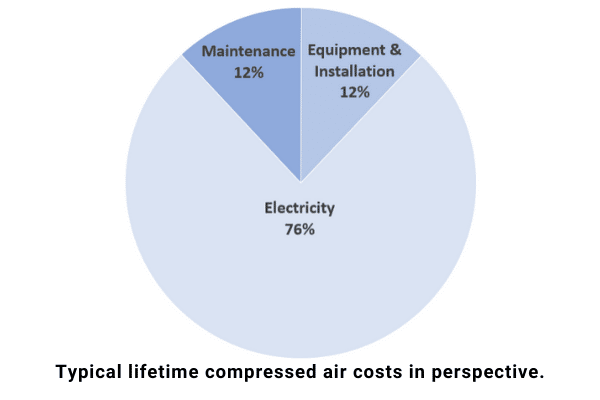
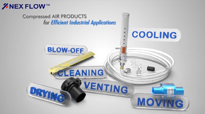
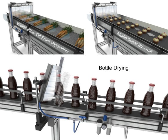
Part of pneumatic technology is the use of compressed air for blowing, moving and cooling. The rugged nature and general low cost of compressed air products for these applications as well as the extremely low level of maintenance required have become more important criteria where downtime and maintenance costs have also risen dramatically especially when compared to more complex and expensive capital cost alternatives.
Pneumatic and hydraulic systems have many similarities. Both pneumatics and hydraulics are applications of fluid power. They each use a pump as an actuator, are controlled by valves, and use fluids to transmit mechanical energy. The biggest difference between the two types of systems is the medium used and applications. Pneumatics use an easily compressible gas such as air or other sorts of suitable pure gas—while hydraulics uses relatively incompressible liquid media such as hydraulic or mineral oil, ethylene glycol, water, or high temperature fire-resistant fluids. Neither type of system is more popular than the other because their applications are specialized. This article will help you make a better choice for your application by describing the two types of systems, their applications, advantages, and disadvantages. The load or the force that you need to apply, the output speed, and energy costs determine the type of system you need for your application.
What is Pneumatics?
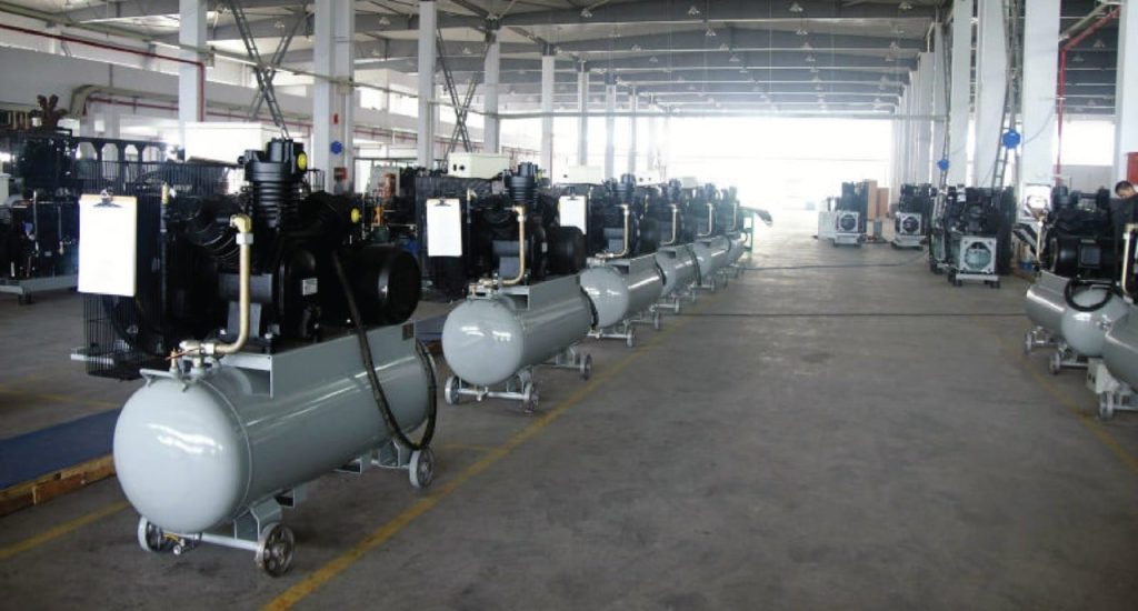
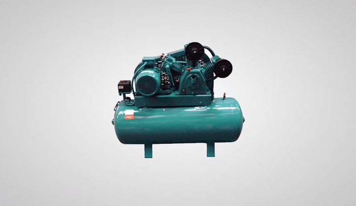
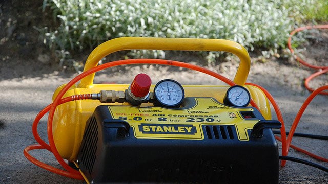
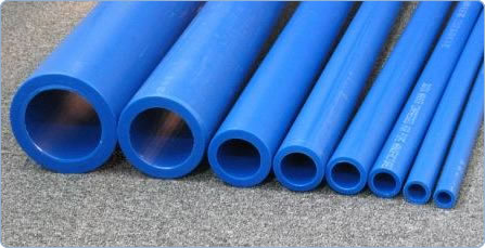
Pneumatics is a branch of engineering that makes use of pressurized gas or air to affect mechanical motion based on the working principles of fluid dynamics and pressure. The field of pneumatics has changed from small handheld devices to large machines that serve different functions. Pneumatic systems are commonly powered by compressed air or inert gases. The system consists of interconnected set of components including a gas compressor, transition lines, air tanks, hoses, standard cylinders, and gas (atmosphere). The compressed air is supplied by the compressor and transmitted through a series of hoses. The air flow is regulated by manual or automatic solenoid valves and the pneumatic cylinder transfers energy provided by the compressed gas to mechanical energy. A centrally located and electrically powered compressor powers cylinders, air motors, and other pneumatic devices. Pneumatic systems are controlled by a simple ON/OFF switch or valve.
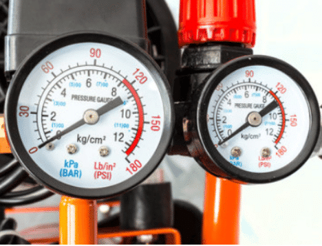
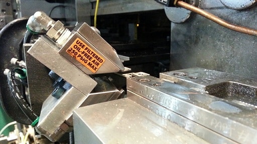
Most industrial pneumatic applications use pressures of about 80 to 100 pounds per square inch (550 to 690 kPa). The compressed air is stored in receiver tanks before it is transmitted for use. The compressors ability to compress the gas is limited by the compression ratios.
Applications
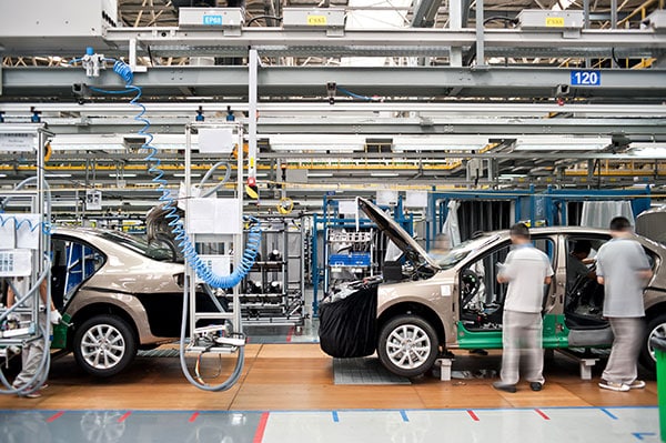
Pneumatic systems are typically used in construction, robotics, food manufacturing and distribution, conveying of materials, medical applications (dentistry), pharmaceutical and biotech, mining, mills, in buildings, and tools in factories. Pneumatic systems are primarily used for shock absorption applications because gas is compressible and allows the equipment to be less susceptible to shock damage.

Applications of pneumatic systems include:
- Air compressors
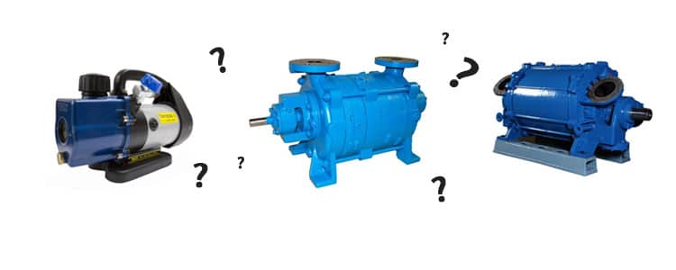
- Vacuum pumps
- Compressed-air engines and vehicles
- HVAC control systems
- Conveyor systems in pharmaceutical and food industries
- Pressure sensor, switch and pump
- Precision drills used by dentists
- Air brakes used by buses, trucks, and trains
- Tampers used to pack down dirt and gravel
- Nail guns
- High pressure bank’s drive-teller tubes
- Manufacturing and assembly lines
- Pneumatic motor, tire, and tools
Advantages and Disadvantages of Pneumatics
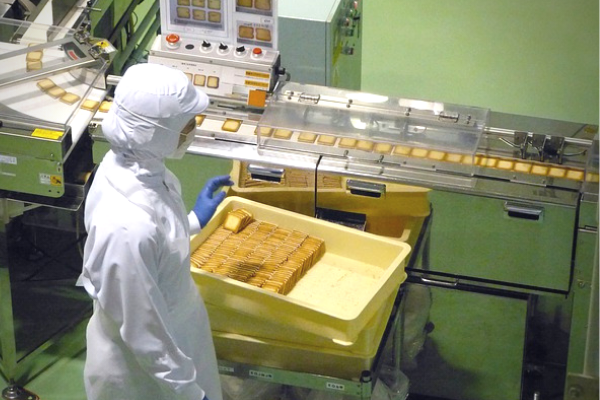
Pneumatic systems are selected above hydraulic systems because of the lower cost, flexibility, and higher safety levels of the system. Pneumatic systems are best suited for applications which require no risk of contamination because they offer a very clean environment for such industries as biotech, dentistry, pharmaceutical, and food suppliers. Since they use clean, dry, compressed air, the system can quickly convey items. The straight and simple design prevents clogging and reduces maintenance. Pneumatic systems are easy to install and portable. They are reliable and has an initial low setup cost because they operate on comparatively low pressure and inexpensive components that reduces operation costs.
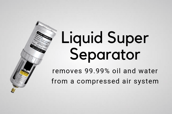
No container is required to store the air that will be compressed because it is drawn from the surrounding atmosphere and filtered (optional). The entire system is designed using standard cylinders and other components. The air or gas used in a pneumatic system is typically dried and free of moisture so that it does not create issues to internal components.
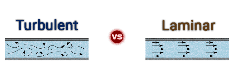
Pneumatic systems provide rapid movement of cylinders because the air compressor flow rates. Air is very agile and can flow through pipes very easily and quickly with little resistance. Pneumatic systems are available in a wide variety in very small sizes. The pneumatic systems are clean and do not pollute because any exhaust is released into the atmosphere. The Pneumatic system is more agile because if the system needs to change directions, the simple design and control allows operators to update the system quickly without environmental impact.
Pneumatics are cheaper than hydraulic systems because air is inexpensive, plentiful, easy to obtain, and store. Pneumatic systems generally have long operating lives and require little maintenance because gas is compressible, and the equipment is less subject to shock damage. Unlike hydraulic systems that use liquids that transfers force, gas absorbs excessive force.
Safety is an important advantage of choosing Pneumatic systems. Since Pneumatic systems run on compressed air, there is very little chance of fire compared with explosion or fire hazard of using compressed hydraulic oil. It is also maintenance free since there is little need to replace filters.
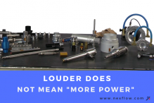
It is essential to determine the amount of force required for your application because not as much force is created with pneumatic systems as with hydraulic systems. Pneumatic systems do not offer the same potential force as hydraulic systems so they should not be used for applications that require lifting or moving heavy loads. Compressed air experiences air pressure fluctuations, so that movement can be jerky or spongy at times while moving or lifting loads. A larger cylinder is needed to produce the same force that a hydraulic ram can produce. In terms of energy costs, pneumatic systems cost more than hydraulics because the amount of energy lost through heat produced while compressing air. Another significant concern about pneumatic systems is the noise that is created. If used, it is the responsibility of the owners to protect their workers from hearing loss.
What is Hydraulics?
Hydraulics is used for the generation, control, and transmission of power using pressurized liquids. It is a technology and applied science involving mechanical properties and use of liquids. Hydraulic systems require a pump and, like pneumatic systems, uses valves to control the force and velocity of the actuators. Industrial applications of hydraulics use 1 000 to 5 000 psi or more than 10 000 psi for specialized application. The word hydraulics originates from Greek words hydor – water and aulos – pipe. The following equipment is required for a hydraulic system: hydraulic fluid, cylinder, piston, pumps, and valves that control the direction of flow, which is always in one direction.

Hydraulic systems, unlike Pneumatic systems are often large and complex. The system requires more room because a container is required to hold fluid that flows through the system. Since the size of the system is larger, it requires more pressure; making it more expensive than Pneumatic systems. Due to their overall larger size and the incompressibility of oil, hydraulic systems can lift and move larger materials. Hydraulic systems are slower because oil is viscous and requires more energy to move through pipes. During configuration and planning, if the factory or plant has several hydraulic machines, it is ideal to have a central power unit to reduce noise levels.
Applications
Due to the risk of potential hydraulic oil leaks from faulty valves, seals or hoses – hydraulic applications do not apply to anything that would be ingested – such as food and medical applications. They are used in a variety of everyday machine applications:
- Elevators
- Dams
- Machine tools: hydraulic presses, hoppers, cylinders, and rams
- Amusement parks
- Turbines
- Dump truck lift
- Wheelchair lift
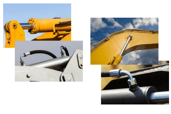
- Excavating arms for diggers
- Hydraulic presses for forging metal parts
- Wing flaps on aircraft
- Hydraulic braking system in cars
- Lift cars using a hydraulic lift
- Jaws of life

Advantages of Hydraulics
Hydraulic systems are more capable of moving heavier loads and providing higher forces due to the incompressibility of liquids. Hydraulic systems do many purposes at one time, including lubrication, cooling, and power transmission. Hydraulic powered machines operate at higher pressures (1 500 to 2 500 psi), generating higher force from small-scale actuators. To effectively use a hydraulic system, it is essential to pick an appropriately sized component to match the flow.
Hydraulic systems are larger and more complicated systems. Liquid, such as hydraulic oil is viscous and requires more energy to move. A tank is also required to store the oil from which the system can draw from when the oil is reduced. The initial costs are higher than Pneumatic systems because it requires power that needs to be incorporated into the machine.
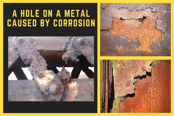
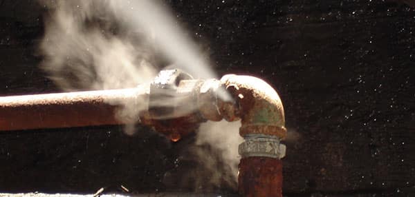
Any leaks in a hydraulic system can cause serious problems. This system cannot be used for food applications due to high risk of hydraulic oil leaks from faulty seals, valves, or burst hoses. Appropriate plumbing procedures, preventative and regular maintenance, and having the correct materials on hand to minimize potential leaks and to quickly remedy any issues need to be in place at each site. In conclusion, pneumatic devices are best suited to execute low scale engineering and mechanical tasks while hydraulic systems are best for applications that require higher force and heavy lifting.
Summary:
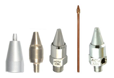
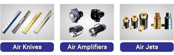
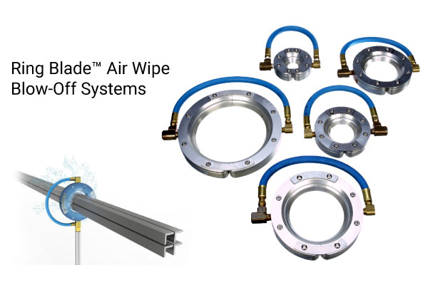
In general, it is a good rule of thumb to use hydraulic systems primarily for heavy lifting applications such as the jaws of life, elevators, hydraulic presses and arms in heavy equipment, and wing flaps for airplanes because these types of systems operate at higher pressures (1 500 to 2 500 psi), generating higher force from small-scale actuators. When it comes to moving or manufacturing products, especially food or pharmaceutical, it is recommended to use pneumatic systems because there is no chance of contamination due to burst pipes or oil leaks. Nex Flow Air Products Corporation manufactures compressed air products for blow off, industrial cooling (Vortex Tubes), air operated conveying, and air optimization designed to reduce energy costs while improving safety and increasing productivity in your factory and manufacturing environments.
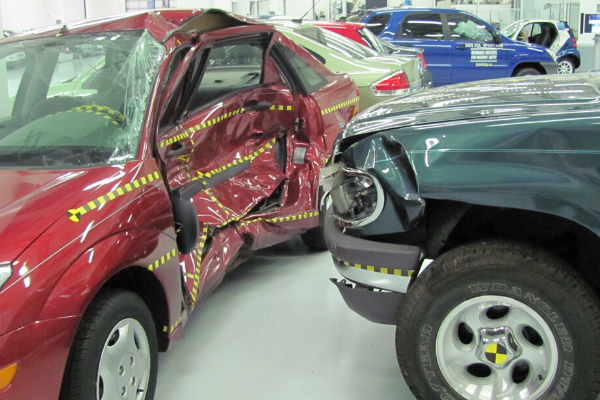
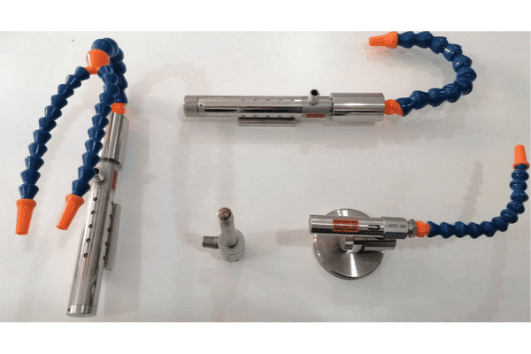
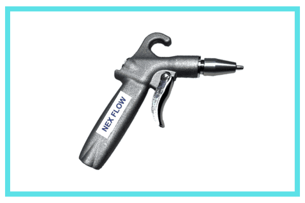
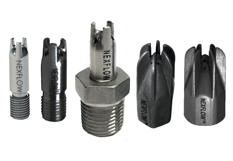
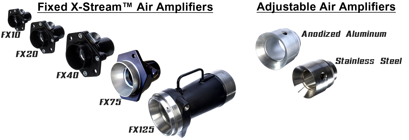
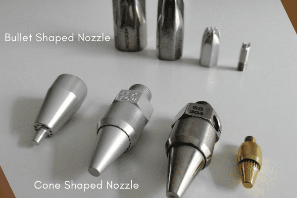
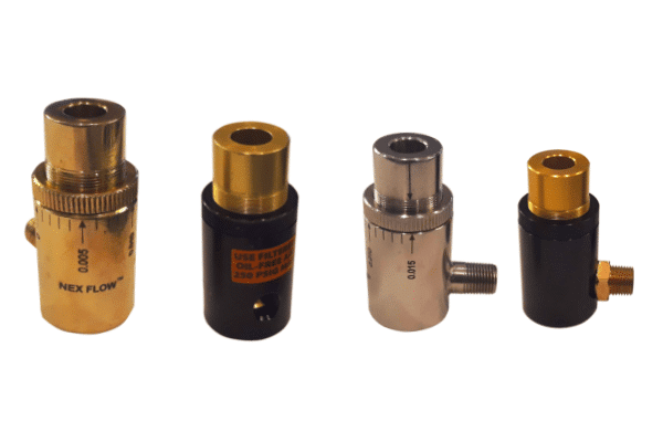
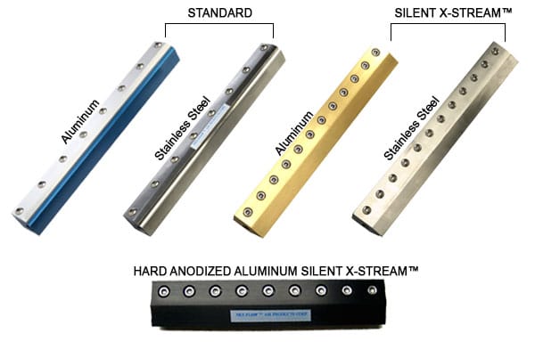
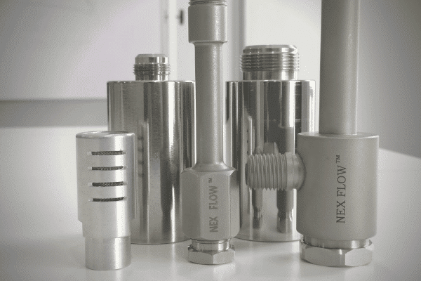
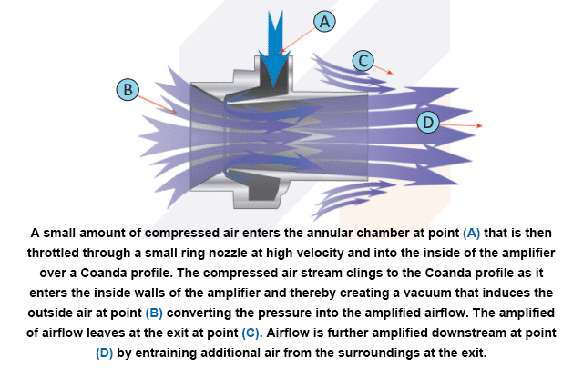
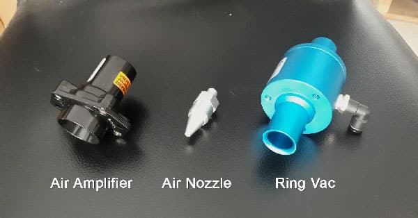
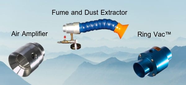
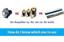
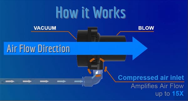
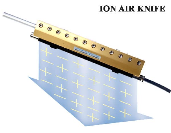
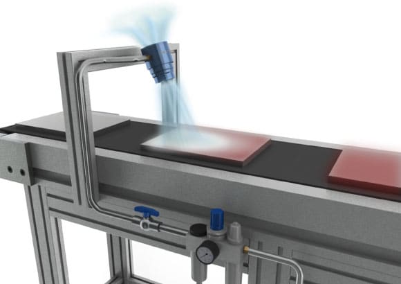
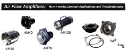
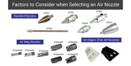
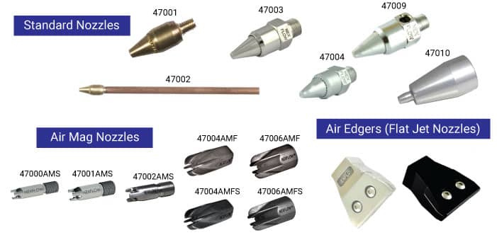
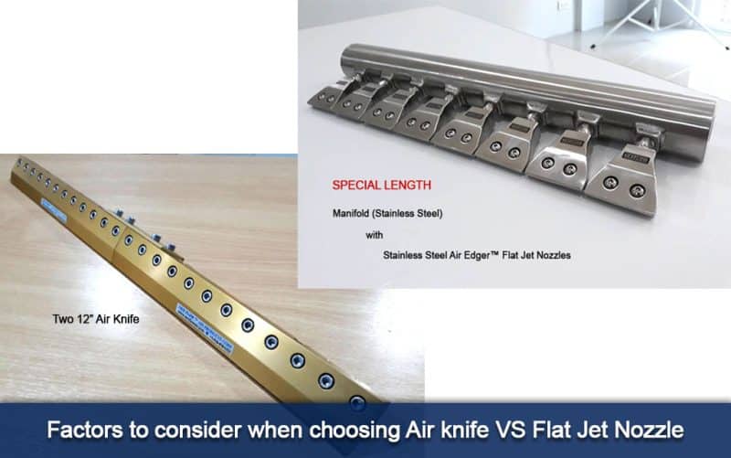
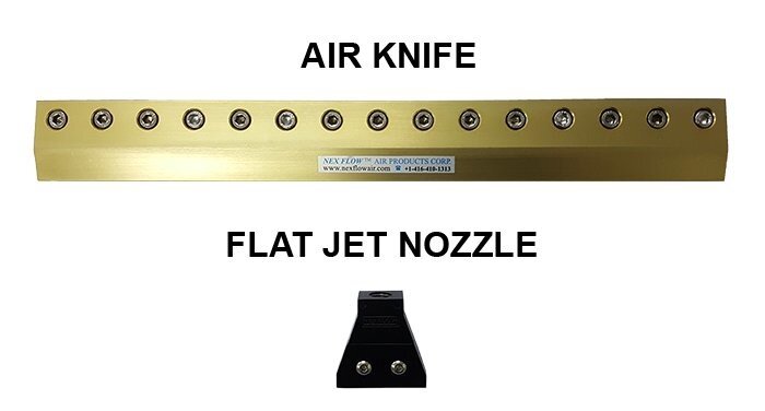
Engineered air jets, air knives, air amplifiers, and air nozzles are examples of blow off products manufactured and sold by Nex Flow. They are safe because they meet OSHA noise and pressure requirements. Air Amplifiers are recommended for purging tanks, venting fumes, smoke, lightweight materials from automobiles, truck repair, or from other confined spaces. These products are also used to clean and dry parts, remove chips, and part ejection. They can also be used as effective tools for your manufacturing environment.
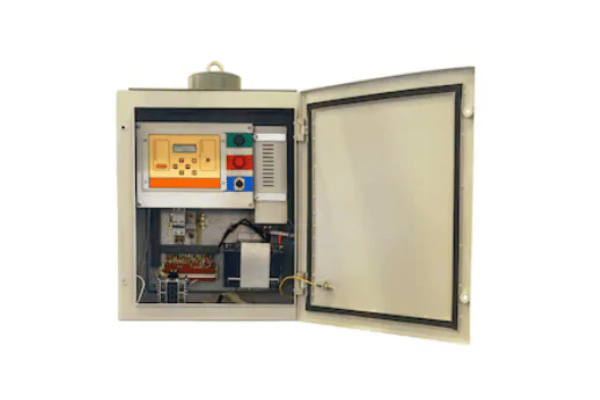
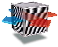
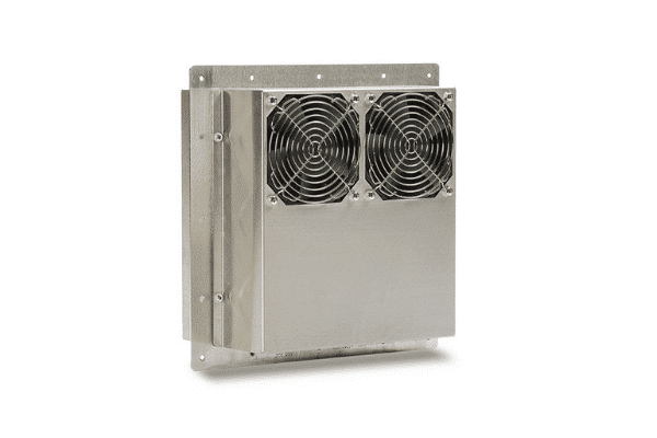
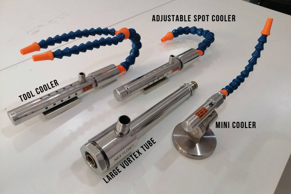
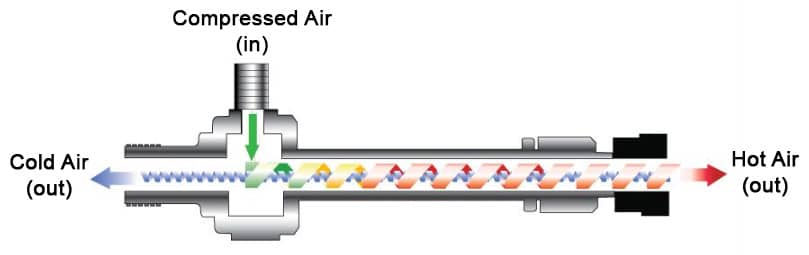
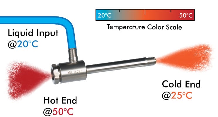
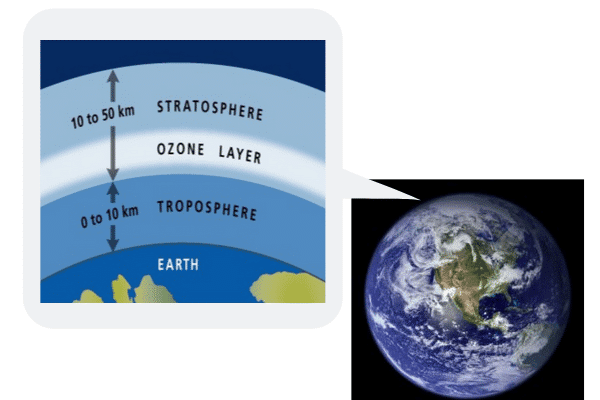
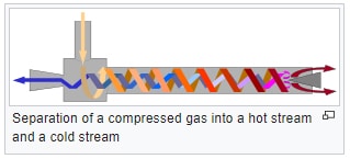
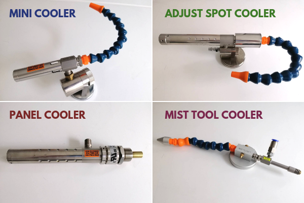
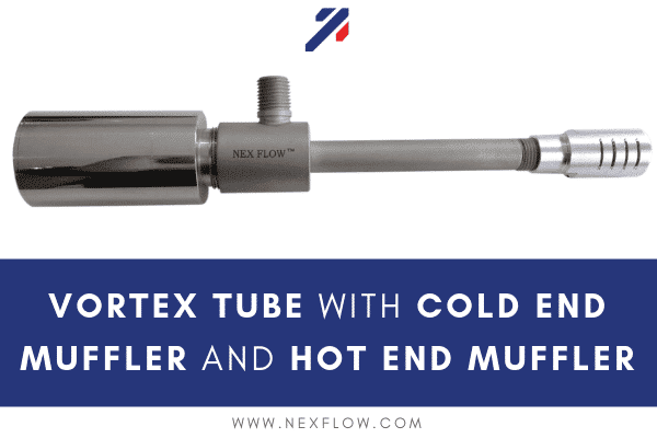
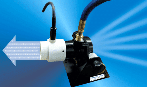
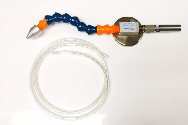
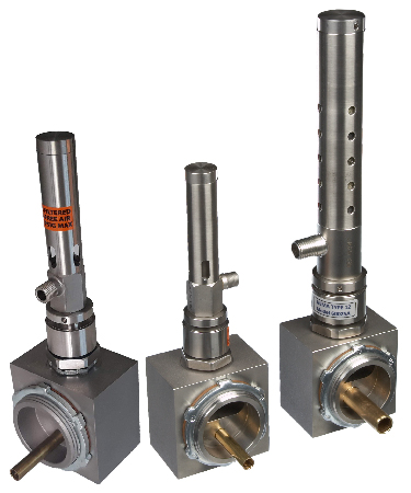
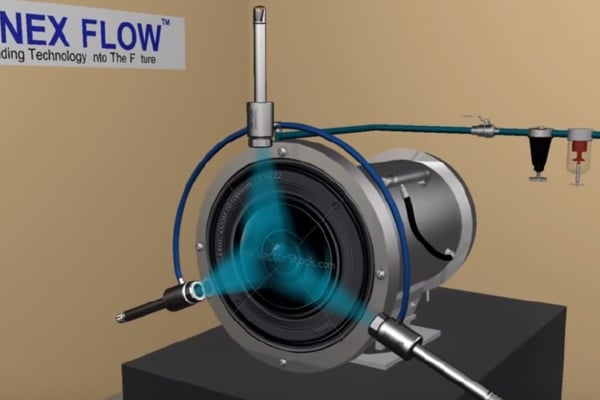
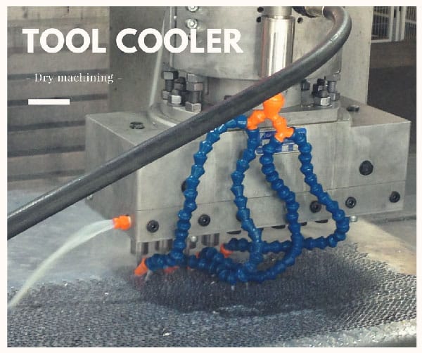
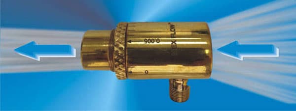
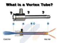
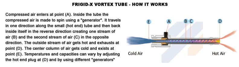
Vortex tube industrial cooling applications converts compressed air into very cold air for spot cooling. Nex Flow provides Vortex Tubes and Cabinet Enclosure Coolers. These products are ideal for use in high temperature and harsh environments. These products are especially ideal for use in high temperature and harsh environments. They also provide smaller vortex tube operated mini-coolers and vortex cooling for tool cooling systems. These systems can provide extremely cold temperatures without the use of refrigerants, such as CFCs or HCFCs. Industrial vortex tube powered cooling products are recommended for cooling gas samples, heat seals, data centers, electronic and electrical control instruments and environmental chambers.
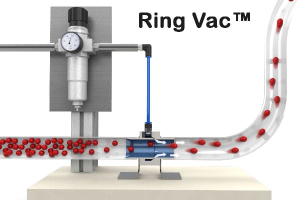
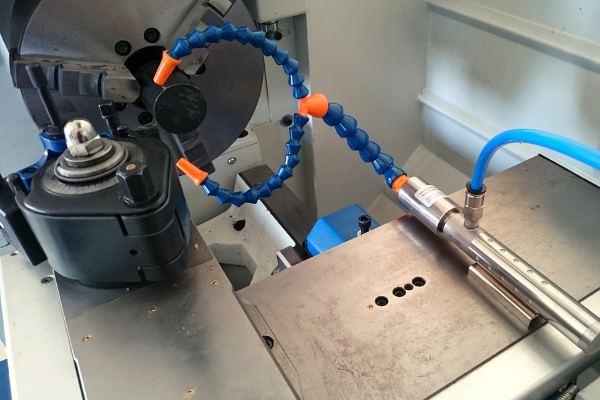
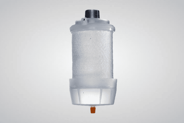
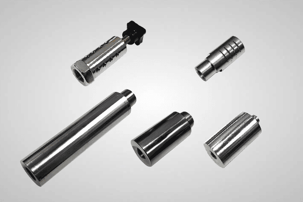
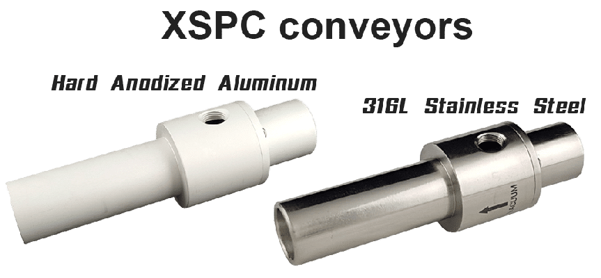
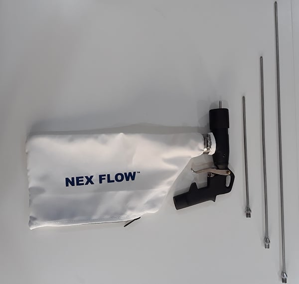
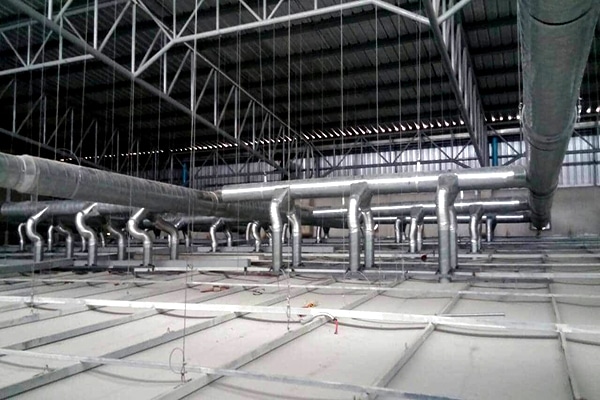
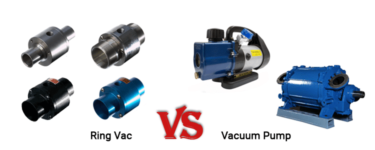
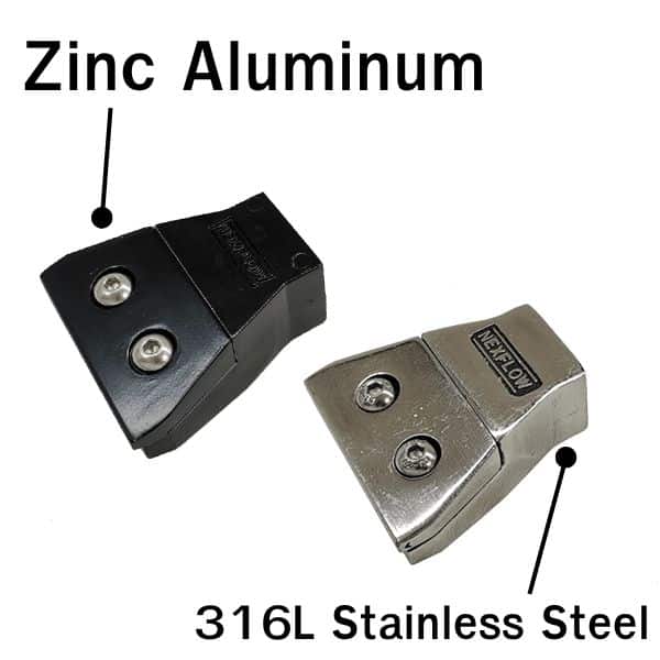
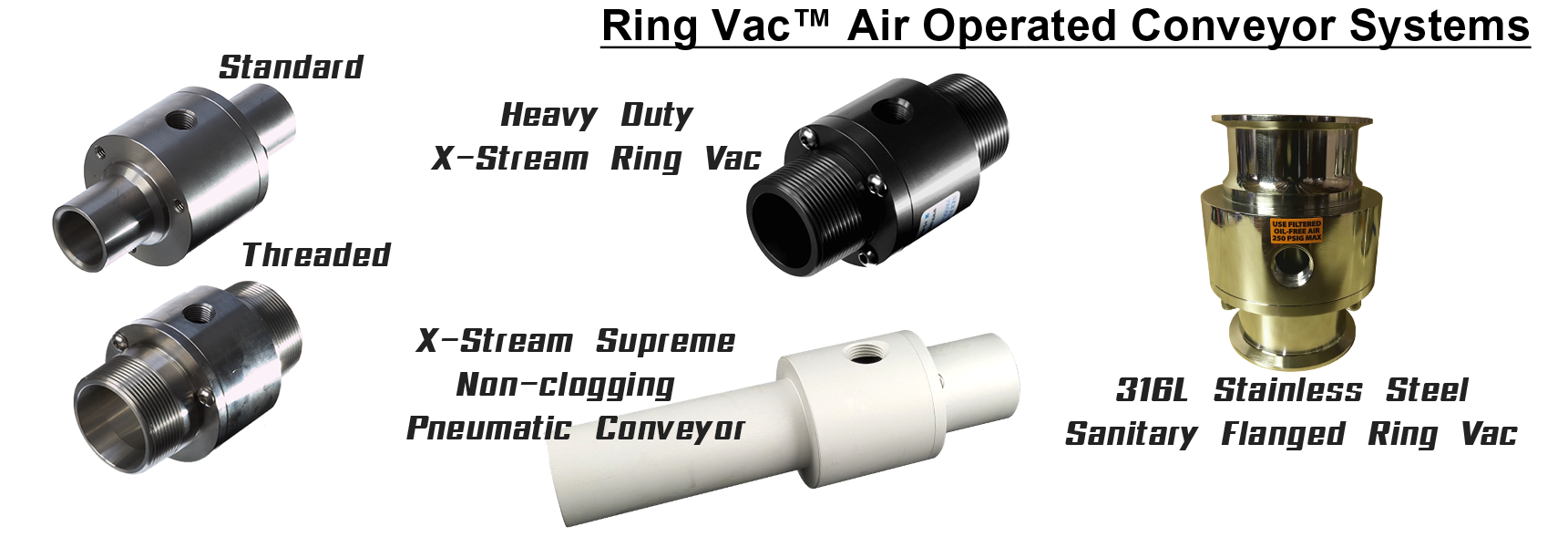
Compressed air operated pneumatic conveyors are designed to move materials at high rates and over long distances. They are ideal for continuous or intermittent use since they are operated by an on/off switch and controlled by a regulator. Our air operated conveyors are compact and have no moving parts. Nex Flow also provides fume and dust extractors, Ring Vac Operated conveyors and an X-StreamTM Hand Vac system. Air operated pneumatic conveyors are primarily used for conveying materials for applications where vacuum force is required to move objects over long distances at high speeds. These devices have an on/off switch to enhance safety. It uses compressed air, not electricity, so there is no explosion hazard. The Nex Flow Ring Vacs are made of anodized aluminum or stainless steel. They are designed to transport or vent a wide variety of lightweight products, raw materials, or fumes from one place to another in your factory. For high temperature and corrosive applications, regular and high temperature stainless steel is available. When moving food and pharmaceutical products, 316L Stainless Steel pneumatic conveyors are used. The specially design non-clogging model XSPC air operated conveyors are easy to install and use, compact and portable, and maintenance free.
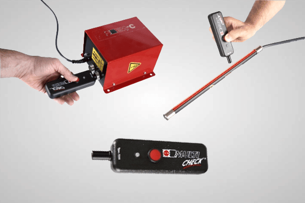
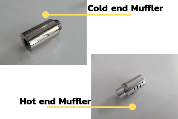
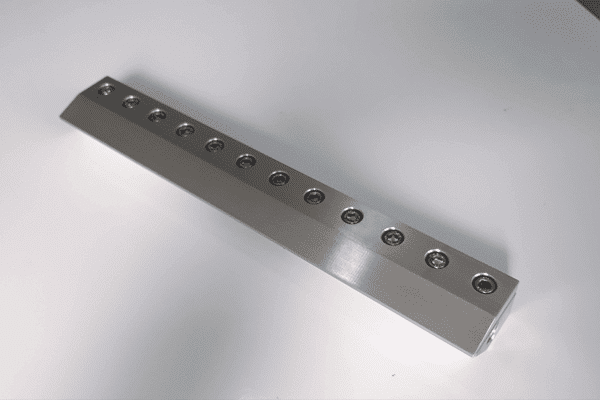
The systems offered by Nex Flow optimize compressed air system operations because of efficient design. The systems can be easily turned on and off so that the compressed air is used only when needed. The products do not have high maintenance costs and are light weight. System optimization can be achieved with the compact sound meter, ultrasonic leak detector and PLC flow control (PLCFC) system for compressed air, which uses photoelectric sensors to turn on the air when the target passes the sensor and to turn off the air when it leaves the sensor or can be set by time. This device can be used for dust and debris blow-off, part drying system, cooling hot parts, and cleaning parts before packaging. Nex Flow offers various accessories that are integrated into pneumatics systems to increase the efficiency of compressed air conveying products and systems. Some accessories include nozzles, mufflers, filters, mounting systems and static control for blow off of dust and debris from statically charged surfaces.
Nex Flow pneumatic products reduce noise, enhance factory safety, and provide excellent venting, cooling, and blow-off solutions. Compressed air conveying systems provides instant response times and are the most efficient and effective way to convert pressure into useful flow. The cost-effective pneumatic conveying systems provided by Nex Flow are simple, light weight, compact, reliable, and easy to install and use. Since there are no moving parts, pockets or angles to collect debris, moisture, or water, the maintenance costs are minimal. Expect the best from Nex Flow technicians, who are trained to help you determine the best solution for your application.